[0010] In this invention, there is possessed the holding mechanism which holds the bezel rotated by a user to a desired position with respect to the case band to the
stationary state at the rotated position. By operating this holding mechanism to thereby exhibit a holding function, it is possible, by restricting the bezel rotated to the desired position, to suppress the fact that this bezel is carelessly rotated by an unexpected external factor and the like to thereby cause a positional deviation. And, in a case where a holding state which makes the bezel stationary is released by operating the holding mechanism, it is possible to rotation-operate the bezel to the desirable rotated position under this released state. By this, it becomes unnecessary to stop the rotation of the bezel by increasing a
frictional resistance force of the gasket. Accordingly, since a
frictional resistance of the gasket against the rotating operation of the bezel is small, it is possible to move the bezel to the desired position by being lightly rotated.
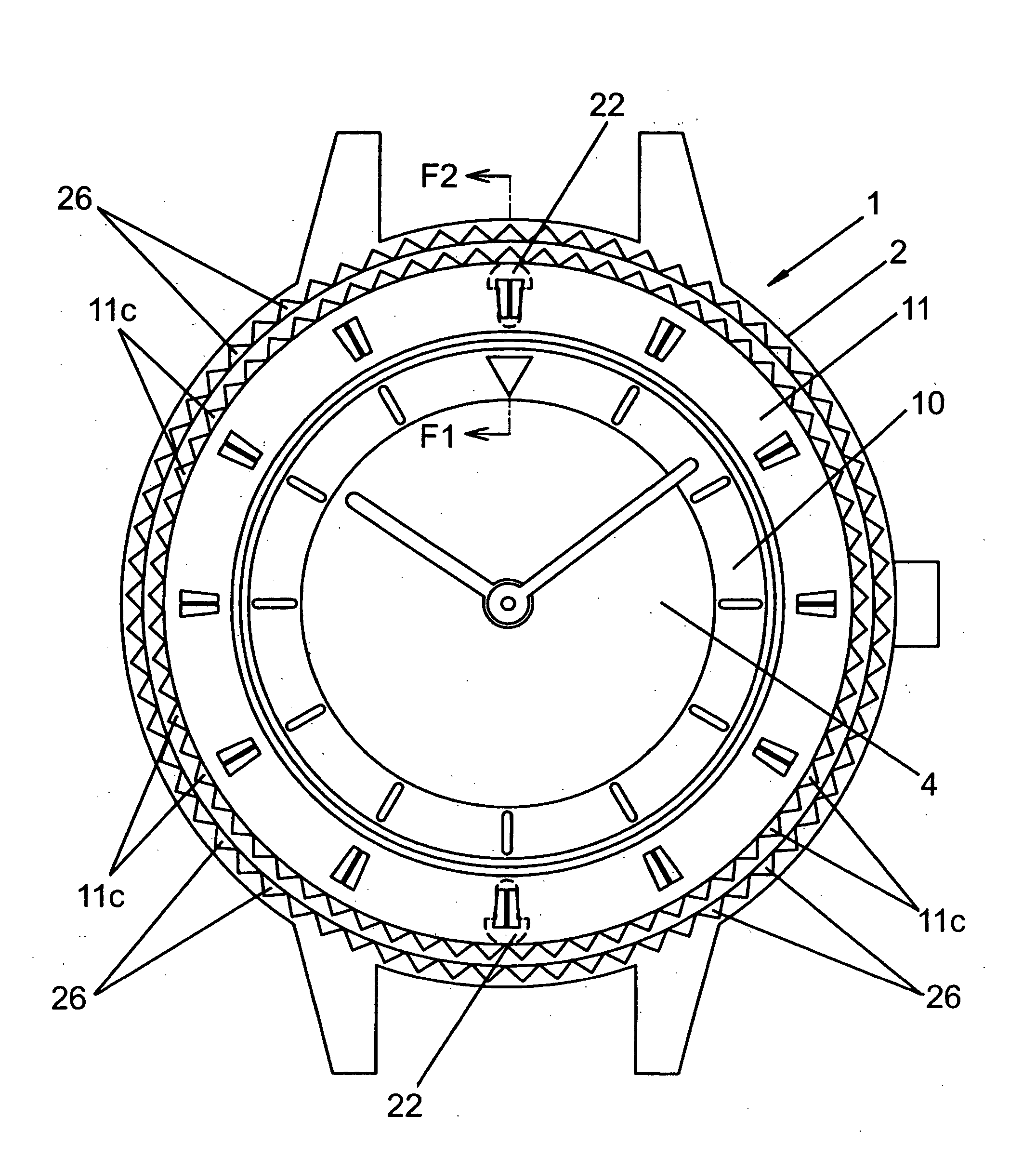
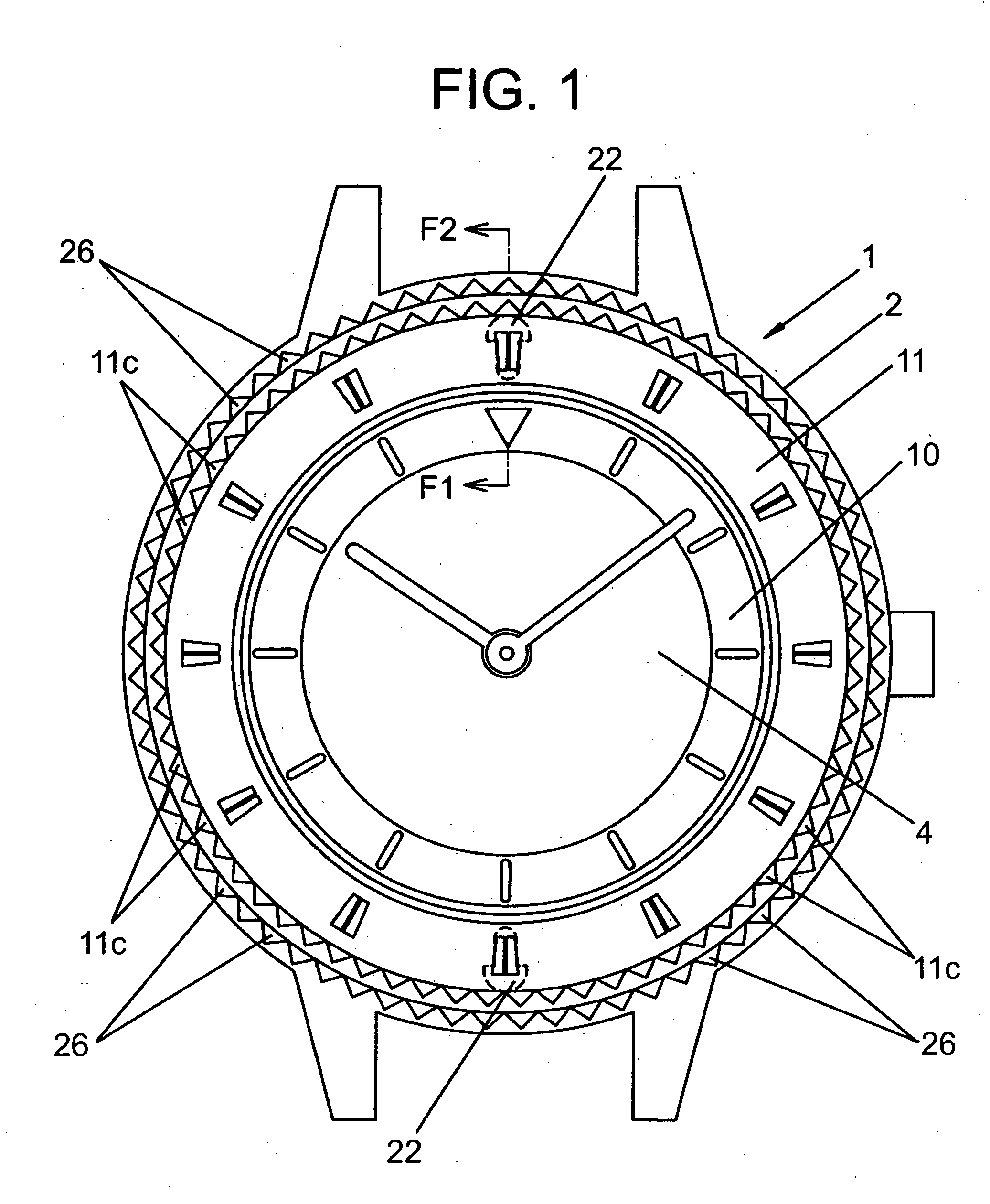
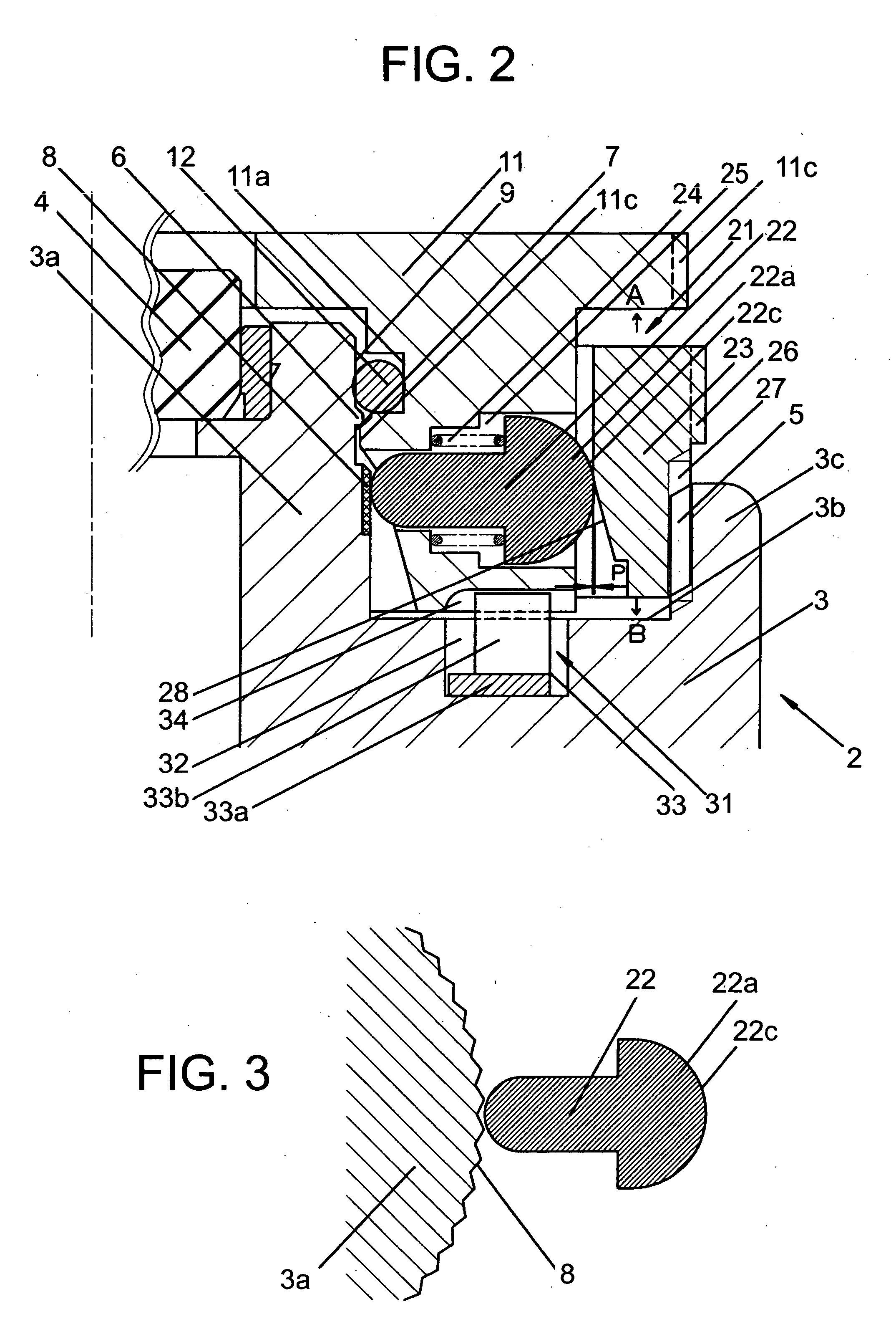
[0011] Further, in a preferred mode of the present invention, the holding mechanism possesses a slip-preventing part provided in the case band, a lock member movably provided in the bezel so as to contact with the slip-preventing part, and a holding ring which has an operating face pressing the lock member to the slip-preventing part and is provided so as to be capable of performing a rotating operation. For this reason, by the rotating operation of the holding ring, lock member can be moved with respect to the bezel through an operating face of the holding ring. With this, it is possible to exhibit a holding function which holds the bezel to the stationary state with respect to the case band by pressing the lock member to the slip-preventing part. Conversely to this, by releasing the pressing by the rotating operation of the holding ring, the function holding the bezel to the stationary state is released and thus the bezel is made possible to be rotation-operated. Like this, it is preferable in a point that the holding mechanism can be operated by the simple rotating operation of the holding ring.
[0012] Further, in a preferred mode of the present invention, since the holding ring is rotatably supported by the case band, it is preferable in a point that the rotation of the holding ring for making the bezel stationary to the desired position is suppressed from being transmitted to the bezel and thus the bezel is not rotated carelessly.
[0013] Further, in a preferred mode of the present invention, since the slip-preventing part is formed by a knurled face provided in the case band, it is preferable in a point that a rotation resistance for making the bezel stationary to the desired position can be obtained in such a manner that the lock member does not slip along the case band, without especially requiring a slip-preventing member.
[0014] Further, in a preferred mode of the present invention, since the slip-preventing part is formed by a hard rubber fixed to the case band, it is preferable in a point that, by obtaining a large
frictional resistance between the slip-preventing part and the lock member, the rotation resistance for making the bezel stationary to the desired position can be obtained in such a manner that the lock member does not slip along the case band.
[0015] Further, in a preferred mode of the present invention, since the holding mechanism has a biasing body which biases the lock member toward the holding ring, it is preferable in a point that, as a holding state of the bezel by the holding mechanism is released, the lock member cab be surely separated from the slip-preventing part and, by this, the lock member can be made so as not to become a hindrance of the rotation when the bezel is rotation-operated.

