
Action for piano

Active Publication Date: 2006-09-14
KAWAI MUSICAL INSTR MFG CO
View PDF8 Cites 10 Cited by
  • Summary
  • Abstract
  • Description
  • Claims
  • Application Information

AI Technical Summary

Benefits of technology

[0012] As described above, after coming into contact with the regulating button, the jack pivotally moves relative to the wippen, while its regulating button contact protrusion is sliding along the jack contact surface, with the counter-force acting from the regulating button. The counter-force of the regulating button in this event is transmitted to the key through the jack and wippen, resulting in a corresponding increase in tough weight. In this sequence of operations, since both the regulating button contact surface and jack contact surface are both flat in the present invention, the regulating button contact surface comes into planar contact with the jack contact surface, to increase the contact area of both, as compared with the aforementioned conventional regulating button contact surface which is curved, resulting in a larger frictional resistance between the regulating button contact protrusion and the regulating button. This makes the regulating button contact protrusion difficult to slide along the jack contact surface to cause consequent difficulties in the pivotal movement of the jack. Thus, the counter-force of the regulating button, transmitted through the jack and wippen, is further increasing until the jack comes off. This results in a larger touch weight immediately before let-off, i.e., a larger let-off load, and a larger amount of change in the touch weight before and after the let-off, thereby making it possible to clarify the timing of the let-off. In response to the thus clarified timing of the let-off, the player can finely adjust a string striking speed of the hammer to realize high playing performance excellent in expressive power. Also, the foregoing advantageous effects can be provided in a simple structure only including the flat jack contact surface and flat regulating button contact surface.
[0013] Preferably, in the action for a piano described above, the regulating button contact surface is angled such that the regulating button contact surface comes into planar contact with the jack contact surface.
[0014] According to this preferred embodiment of the action for a piano, the regulating button contact surface comes into tightly planar contact with the jack contact surface without fail. This causes the generation of a large frictional resistance between the regulating button contact protrusion and the regulating button, which makes the jack difficult to pivotally move, and increases the let-off load, thus making it possible to ensure the advantageous effects mentioned above.
[0015] Preferably, the action for a piano described above further comprises a sheeted damping material on at least one of the jack contact surface or the regulating button contact surface, wherein the regulating button contact surface is angled such that when the regulating button contact surface comes into contact with the jack contact surface through the damping material, the regulating button contact surface comes into contact with an end of the jack contact surface close to the jack fulcrum, and the regulating button contact surface extends obliquely in close proximity to the jack contact surface.
[0016] According to this preferred embodiment of the action for a piano, during a pivotal movement of the wippen associated with a depression on the key, the regulating button contact surface of the regulating button contact protrusion comes into contact with the jack contact surface through the sheeted damping material, causing the jack to pivotally move relative to the wippen. Also, when this contact is made, the regulating button contact surface comes into contact with the end of the jack close to the jack fulcrum, and extends obliquely in close proximity to the jack contact surface, i.e., comes into contact with the jack contact surface at a slight angle formed thereto. In this event, as the intervening sheeted damping material is compressed, a combination of the end of the regulating button contact surface close to the jack fulcrum and its vicinity is in contact with planar contact with the jack contact surface through the damping material, thereby ensuring a larger frictional resistance. Further, such a planar contact causes the center of the planar contact, i.e., a point acted by the counter-force from the regulating point, to be near the jack fulcrum, resulting in a larger counter-force of the regulating button required for the pivotal movement of the jack. Thus, according to the present invention, the let-off load is increased by a larger frictional resistance ensured by the planar contact, and the counter-force of the regulating button acting on a position closer to the jack fulcrum, thus ensuring the advantageous effects of the action described above.
[0017] Preferably, in the action for a piano described above, the jack includes a hammer push-up rod extending upward from the jack fulcrum, and configured to engage with the hammer, and the hammer push-up rod includes a prominence formed along an edge of a top surface thereof opposite to the regulating button contact protrusion.

Problems solved by technology

The counter-force of the regulating button in this event is transmitted to the key through the jack and wippen, resulting in a corresponding increase in tough weight.
This makes the regulating button contact protrusion difficult to slide along the jack contact surface to cause consequent difficulties in the pivotal movement of the jack.

Method used


Image

  • Action for piano
  • Action for piano
  • Action for piano

Examples


first embodiment

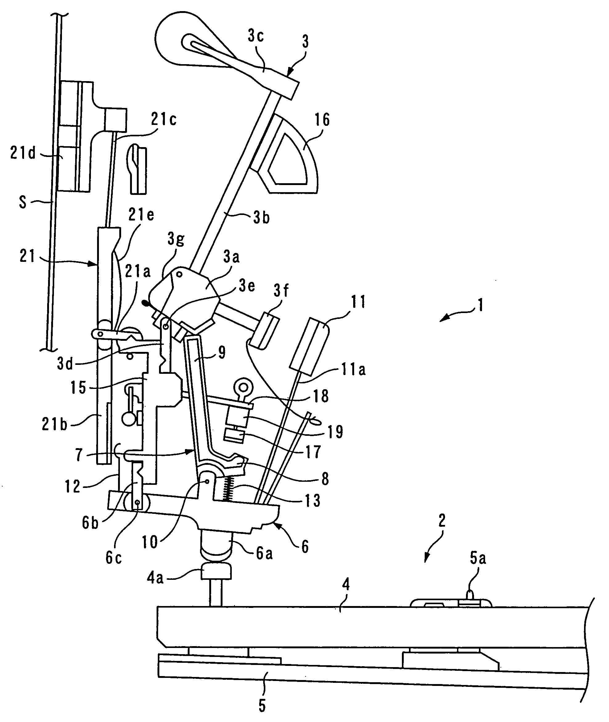
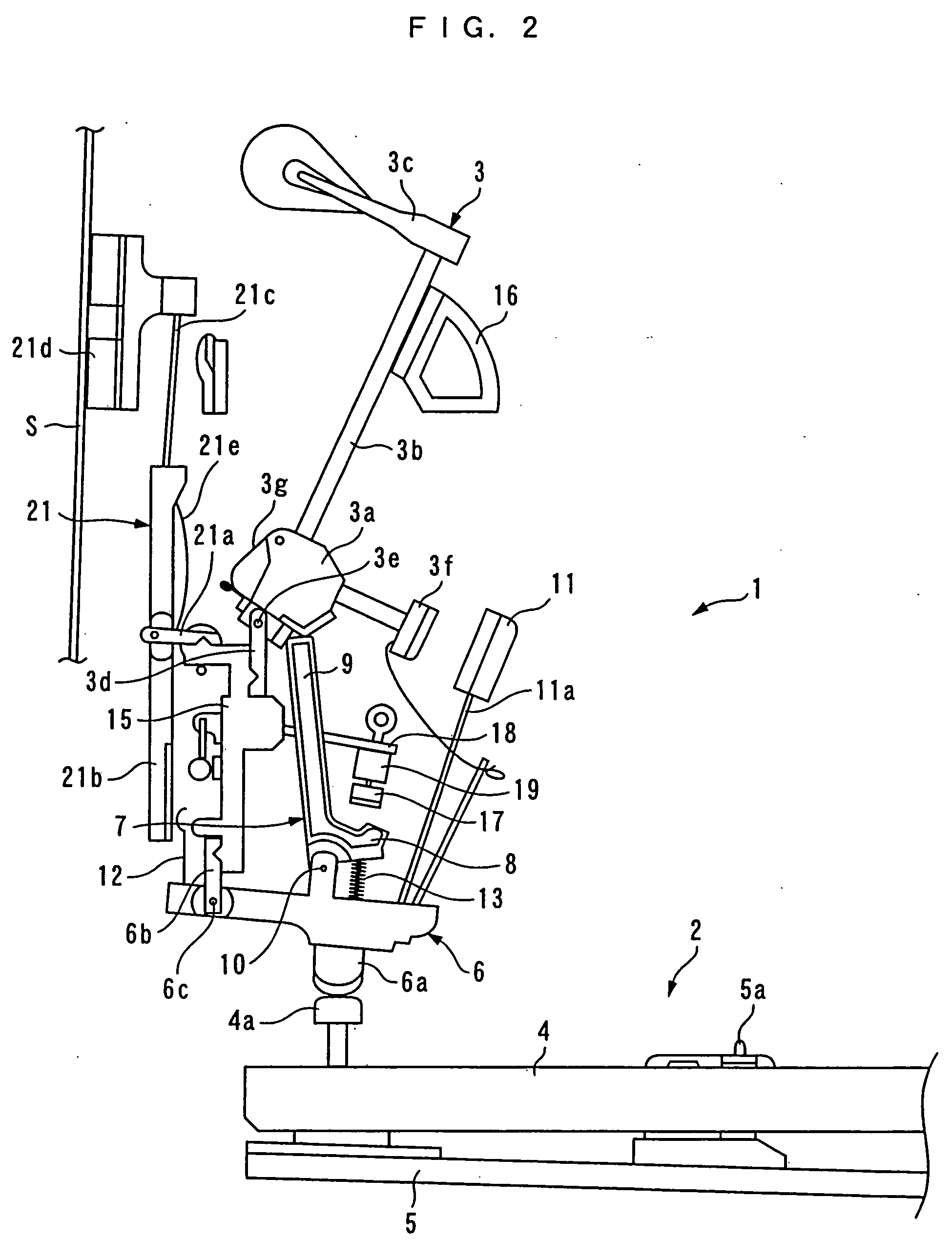
[0039]FIG. 2 illustrates an action 1, a keyboard 2, a hammer 3 and the like of an upright piano according to the present invention in a key released state. The keyboard 2 comprises a large number of keys 4 (only one of which is shown) arranged side by side from left to right (in a depth direction in FIG. 2), and each key 4 is swingably supported by a fulcrum which is a balance pin 5a implanted on a keybed 5.

[0040] The action 1 is attached to a left and a right bracket (none of which is shown) arranged at a left and a right end of the keybed 5 above the rear end of the keyboard 2, and arranged to extend between both the brackets. The action 1 also comprises a wippen 6 and a jack 7 which are provided for each key 4 (only one each of them is shown). Further, a center rail 15 and a hammer rail 16 are extended between the left and right brackets.

[0041] The wippen 6, which is formed, for example, of synthetic resin in a predetermined shape, has a heel 6a extending downward from the front...

second embodiment

[0066] It should be understood that the present invention is not limited to the embodiments described above, but can be practiced in a variety of implementations. For example, in the foregoing embodiments, the regulating button contact surfaces 8a, 41 are completely flat, but they may be slightly curved to such a degree that a sufficient planar contact can be ensured with the jack contact surface 17a. Also, in the foregoing embodiments, the punching 17b is attached to the jack contact surface 17a, but may alternatively or additionally be attached to the regulating button contact surface 8a or 41. Further, in the second embodiment, the prominence 32b is formed across the top surface 32a of the hammer push-up rod 32 in the left-to-right direction, but may be partially formed. Further alternatively, a plurality of such prominences may be formed.

[0067] Also, in the foregoing embodiments, since the jack 7 has a high rigidity, the jack 7 is reduced in weight such that it can promptly retu...


PUM


Abstract

An action for a piano is provided for clarifying a timing of let-off, improving the sequential touching capabilities, and consequently realizing high playing performance excellent in expressive power in a simple structure without adversely affecting the key touch feeling. The action for a piano swings a hammer in response to a touch on a key, and comprises a wippen pushed up by the key to pivotally move, a regulating button having a flat jack contact surface on the lower end, and a jack having a flat regulating button contact surface which comes into contact with the jack contact surface as the key is depressed. The jack comprises a molding made of a thermoplastic resin containing long fibers for reinforcement.

Description

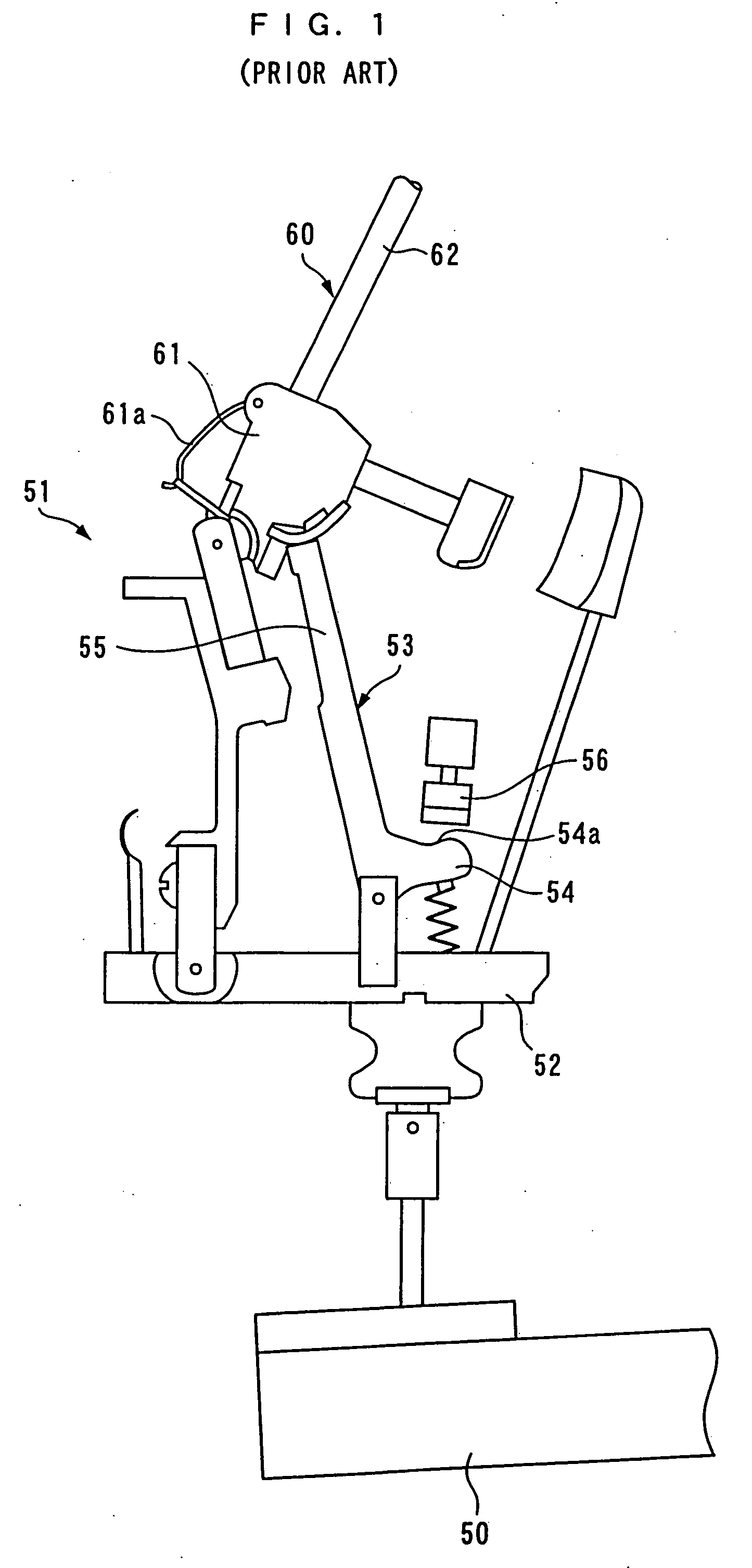
BACKGROUND OF THE INVENTION [0001] 1. Field of the Invention [0002] The present invention relates to an action for a piano which actuates in response to a depression on an associated key to swing a hammer which in turn strikes a string. [0003] 2. Description of the Prior Art [0004] A known conventional action for a piano is disclosed, for example, in Laid-open Japanese Patent Application No. 6-83326. FIG. 1 illustrates main components of an action 51 in a key released state. The action 51 is adapted for an upright piano, and is disposed above the rear end of a key 50 (the left-hand side in FIG. 1 is assumed to be the rear side). The action 51 comprises a wippen 52 carried on the rear end of the key 50; a jack 53 pivotably arranged on the wippen 52; and a regulating button 56 disposed at a predetermined position above the wippen 52. The jack 53 is formed in L-shape with a regulating button contact protrusion 54 extending in the front-to-rear direction, and a hammer push-up rod 55 ext...

Claims


Application Information

Patent Timeline
IPC IPC(8): G10C3/18
CPCG10C3/161G10C1/02G10C9/00
Inventor TANAKA, KOUSUKE
Owner KAWAI MUSICAL INSTR MFG CO
Learn More