Damper having torque limiter function

a torque limiter and torque technology, applied in the field of wet type dampers, can solve the problems of over-expansion of critical torque at which the torque transmission is blocked, excessive torque may damage the damper and other mechanisms in the torque transmission path, and inevitably enlarge each mechanism, so as to reduce impact torque, reduce torque, and reduce the effect of impact torqu

Active Publication Date: 2011-08-11
AISIN AW INDUSTRIES CO LTD
View PDF15 Cites 8 Cited by
  • Summary
  • Abstract
  • Description
  • Claims
  • Application Information

AI Technical Summary

Benefits of technology

[0052]Further, when the damper springs are compressed and deformed by a certain degree, the second friction member is rotated, and the second friction member to which biasing force is applied contacts the central disc or the two plates and generates a large frictional resistance. Accordingly, the damper alleviates the impact torque and absorbs energy produced by the impact torque. This readily attenuates and stops the elastic motion of the damper springs.

Problems solved by technology

This may overly increase the torque (critical torque) at which torque transmission is blocked.
As a result, excessive torque may inflict damages to the damper and other mechanisms in the torque transmission path.
This inevitably enlarges each mechanism.
In contrast, however, a large impact torque may not be sufficiently alleviated if the spring constant is lowered.
Further, the energy of the impact torque cannot be readily absorbed just with the damper spring 311.

Method used


Image

  • Damper having torque limiter function
  • Damper having torque limiter function
  • Damper having torque limiter function

Examples


first embodiment

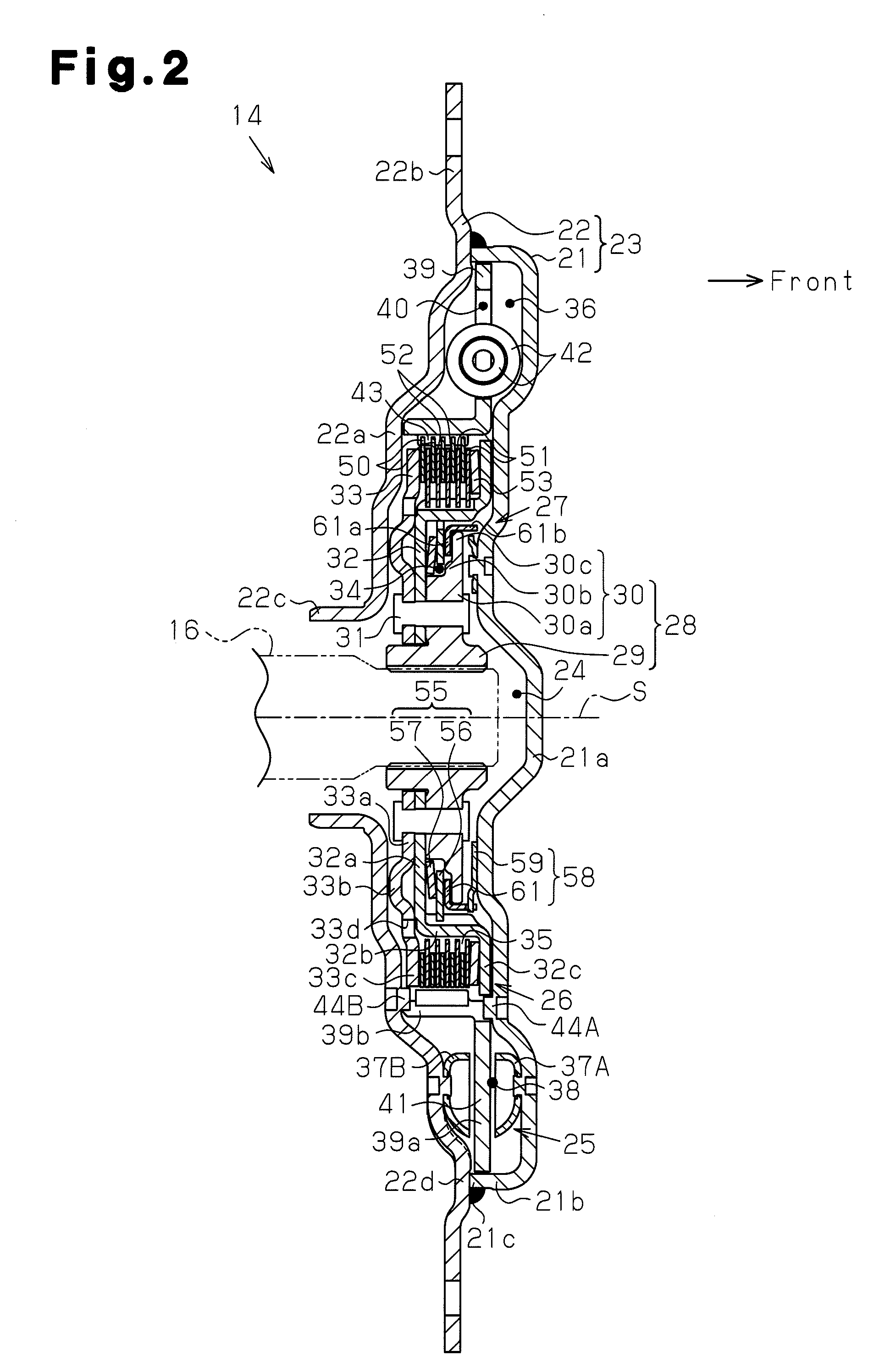
[0066]a damper, which is installed in a hybrid vehicle, according to the present invention will now be discussed with reference to FIGS. 1 to 5. In the description of the present specification hereinafter, the “front side” refers to the right side as viewed in FIG. 2, and the “rear side” refers to the left side as viewed in FIG. 2.

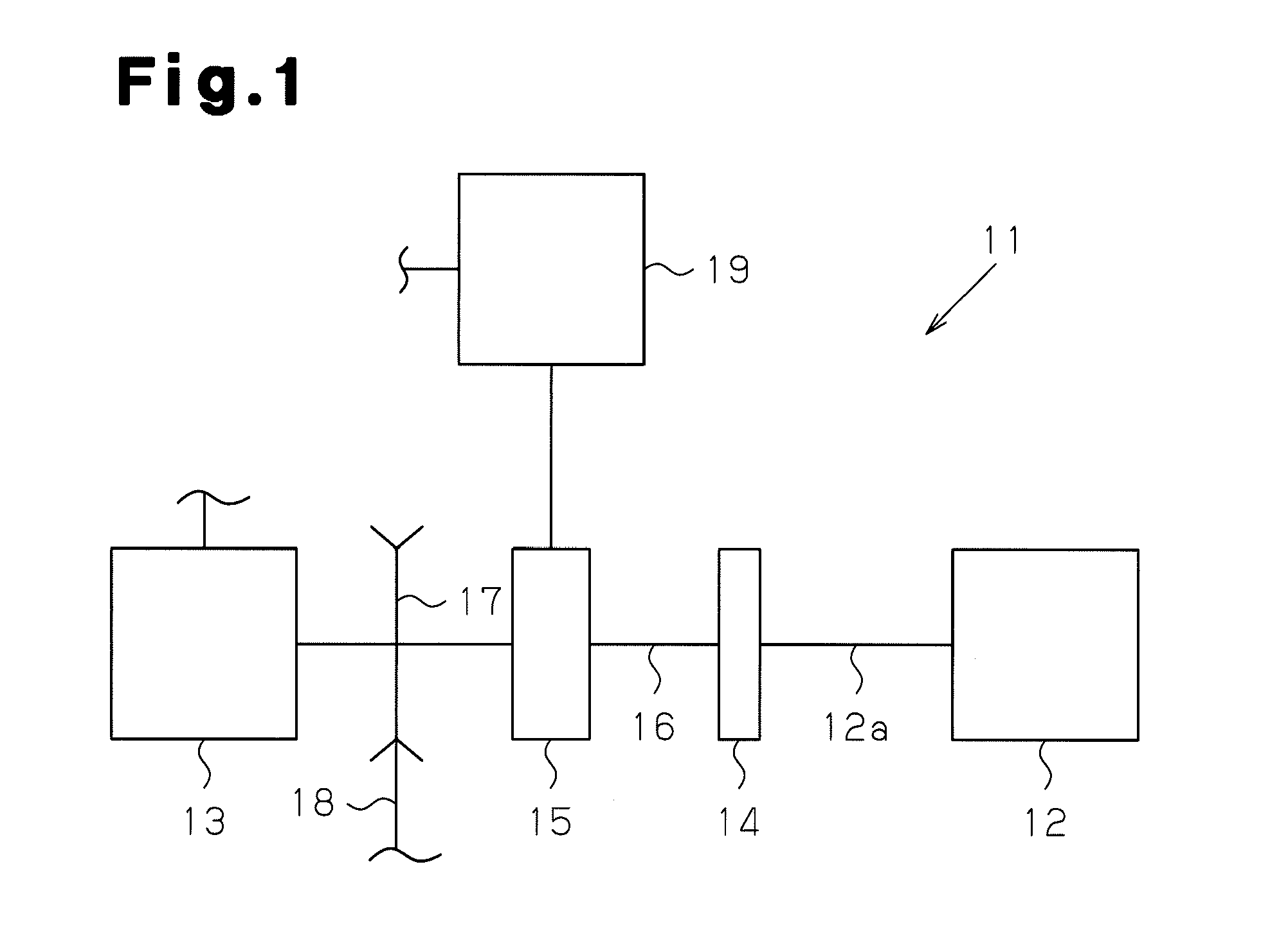
[0067]As shown in FIG. 1, a hybrid drive device 11 mounted on the hybrid vehicle includes an engine 12, which is a first power source, an electric motor 13, which is a second power source driven by power supplied from a battery (not shown), and a damper 14, which absorbs fluctuation in the torque generated by the engine 12 and the electric motor 13 (hereinafter referred to as “torque fluctuation”). The hybrid drive device 11 also includes a planetary gear mechanism 15, to which the torque from the engine 12 transmitted via the damper 14 and the torque from the electric motor 13 are transmitted.

[0068]The planetary gear mechanism 15 includes a sun gear, a pi...

second embodiment

[0117]the present invention will now be discussed with reference to FIGS. 7 to 12.

[0118]FIG. 7 is a cross-sectional view showing a damper 114 according to the present invention. In FIG. 7, reference number 101 denotes a damper device, reference number 102 denotes a limiter plate, reference number 103 denotes a limiter disc spring serving as a first biasing member, and reference number 23 denotes an outer case serving as a housing. The damper 114 has the same basic structure as a damper used in a torque converter. The damper 114 includes a plurality of damper springs 42. Each damper spring 42 is arranged between a first plate 106 and a second plate 107 and accommodated in a spring accommodation hole 40 formed by the first plate 106 and the second plate 107. Each of the first plate 106 and the second plate 107 has an inner circumference portion that is located radially inward from the spring accommodation hole 40 and an outer circumferential portion that is located radially outward fr...

third embodiment

[0139]FIG. 12 is a cross-sectional view showing a damper according to the present invention. In FIG. 12, reference numeral 139 denotes a central disc, reference numeral 140 denotes a first plate, reference numeral 141 denotes a second plate, and reference numeral 142 denotes an output side disc serving as a torque output side portion.

[0140]The central disc 139 is arranged between and fixed by the first plate 140 and the second plate 141. The central disc 139, the first plate 140, and the second plate 141 form a torque input side portion. The output side disc 142, which serves as the torque output side portion, is arranged on the inner circumferential side of the substantially ring-shaped central disc 139. The output side disc 142 is arranged between the first plate 140 and the second plate 141.

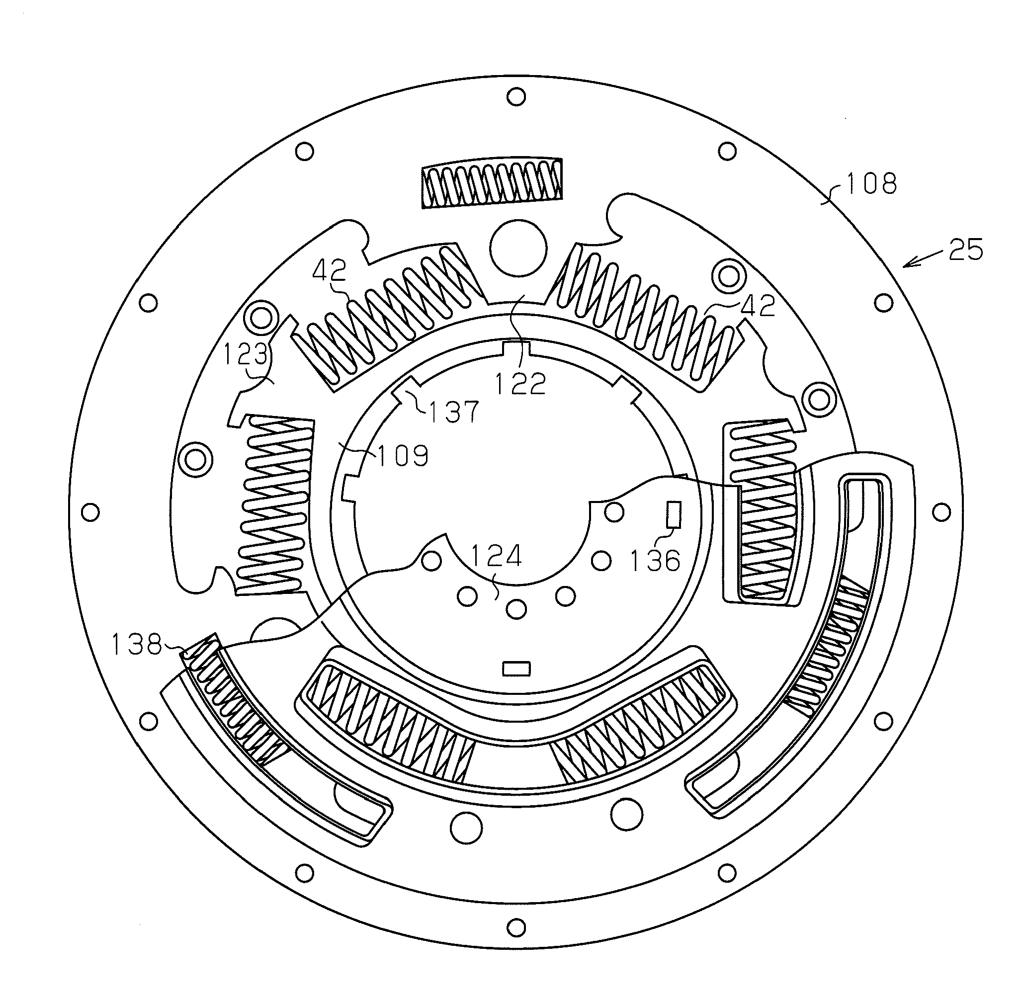
[0141]A damper spring 42 is accommodated in a spring accommodation hole 40 formed by the first plate 140 and the second plate 141. The output side disk 142 has an inner circumference portion t...


PUM


Abstract

A damper includes an outer cover having a front cover and a rear cover. The covers are joined to form a lubricant oil accommodation chamber for accommodating liquid. A damper device, a limiter mechanism, a first plate including a first collar portion located toward the front of the limiter mechanism, and a second plate including a second collar portion located toward the rear of the limiter mechanism are arranged in the outer cover. The limiter mechanism includes a first limiter plate, which is an input side on the torque transmission path, a second limiter plate, which is an output side on the torque transmission path, and a limiter disc spring, which presses the limiter plates.

Description

TECHNICAL FIELD[0001]The present invention relates to a wet-type damper capable of absorbing torque vibration generated at a power source such as an engine and having a torque limiter function.BACKGROUND ART[0002]In a vehicle, a damper is usually arranged in a torque transmission path to absorb torque vibration, which is generated at a power source such as an engine or an electric motor. When a large torque is generated at the power source, such a damper blocks the transmission of torque from one side of the torque transmission path to the other side of the torque transmission path with a limiter mechanism (see Japanese Laid-Open Patent Publication No. 2008-274968).[0003]Japanese Laid-Open Patent Publication No. 2008-274968 describes a damper (hereinafter referred to as “conventional damper”), which is of a wet-type damper used in a so-called hybrid vehicle, which uses an engine and an electric motor as a power source. As shown in FIG. 13, the conventional damper includes an outer c...

Claims


Application Information

Patent Timeline
Patent Type & Authority Applications(United States)
IPC IPC(8): F16F15/123F16D3/00
CPCF16F15/10F16F15/163F16F15/1297F16F7/02
Inventor TAKESHITA, YOSHITODOSEKI, FUMIAKIYAMAGUCHI, MASAHIROYAMAGUCHI, MASAAKISUZUKI, TAKUONAGA, TETSUYA
Owner AISIN AW INDUSTRIES CO LTD
Why Eureka
Try Eureka