Pusher guide wire

a guide wire and pusher technology, applied in the field of pusher guide wires, can solve the problems of retrieving into the catheter, unable to redo the procedure, etc., and achieve the effect of reducing the risk of the stent being caught by the stent holding portion

Inactive Publication Date: 2016-04-14
ASAHI INTECC CO LTD
View PDF9 Cites 5 Cited by
  • Summary
  • Abstract
  • Description
  • Claims
  • Application Information

AI Technical Summary

Benefits of technology

[0010]A frictional resistance between the stent and the stent holding portion of the pusher guide wire is larger at a proximal end portion of the stent holding portion than at a distal end portion of the stent holding portion. Since the frictional resistance between the stent and the stent holding portion is smaller at the distal end portion of the stent holding portion, a risk of the stent being caught by the stent holding portion is reduced when the stent is released to the target site from the distal end of the catheter. Additionally, since the frictional resistance between the stent and the stent holding portion is larger at the proximal end portion of the stent holding portion, when the technician notices that the delivering position of the stent is displaced from the target site and pulls the pusher guide wire in the proximal direction, the stent in the course of being released can be retrieved into the catheter (in other words, the procedure can be redone). Furthermore, since the frictional resistance between the stent and the stent holding portion is smaller at the distal end portion of the stent holding portion, when the stent is retrieved into the catheter, a risk of the stent coming into contact with the stent holding portion and becoming deformed is reduced; accordingly, the technician can repeatedly retrieve the stent into the catheter until the delivery position of the stent coincides with the target site.

Problems solved by technology

Accordingly, even when a technician that has started to release the stent to the target site from the distal end of the catheter notices that the delivering position of the stent is displaced from the target site and pulls the pusher guide wire in the proximal direction, because the frictional resistance between the stent and the stent holding portion is small, the stent disadvantageously cannot be retrieved into the catheter (in other words, the procedure cannot be redone).

Method used


Image

  • Pusher guide wire
  • Pusher guide wire
  • Pusher guide wire

Examples


Embodiment Construction

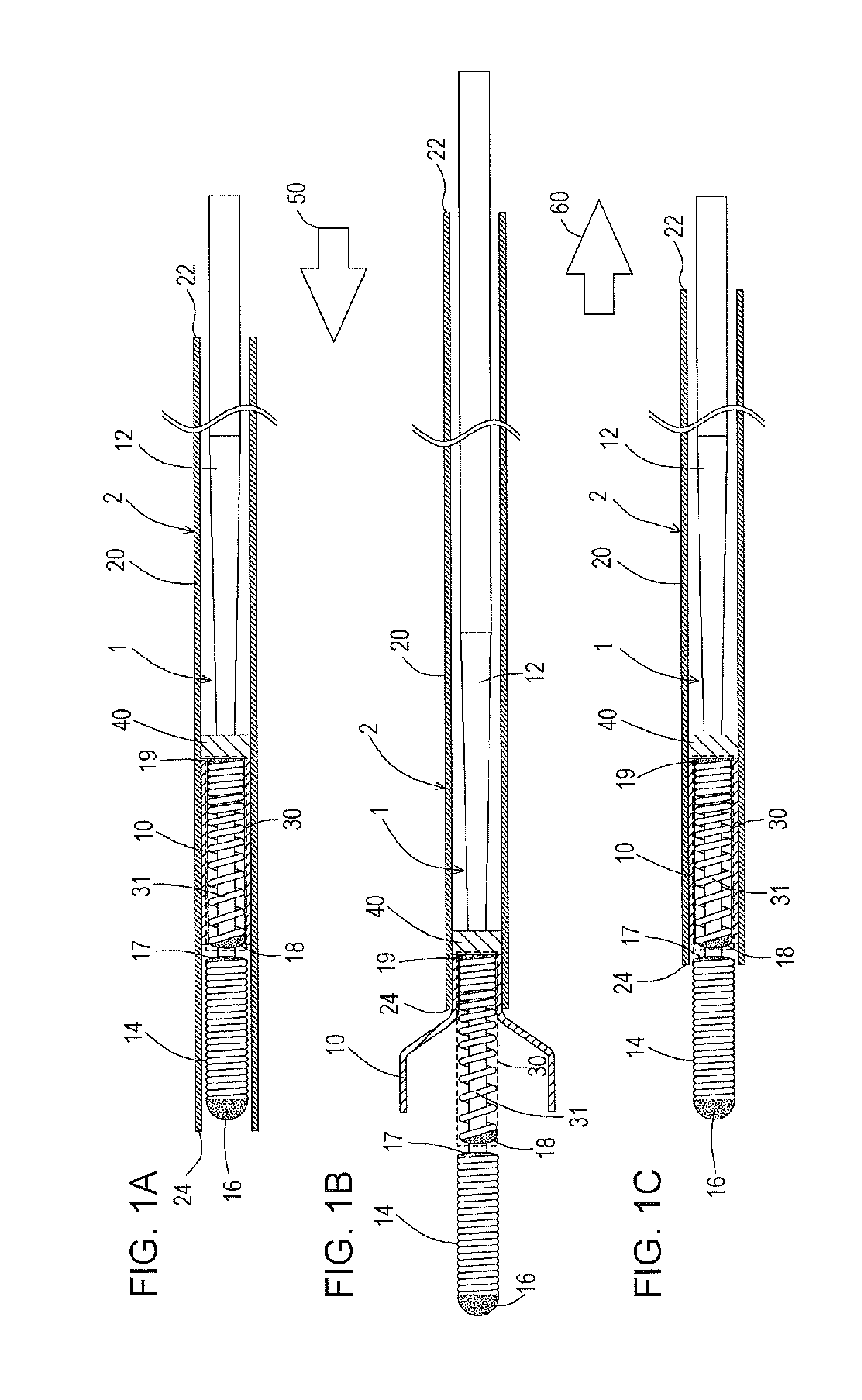
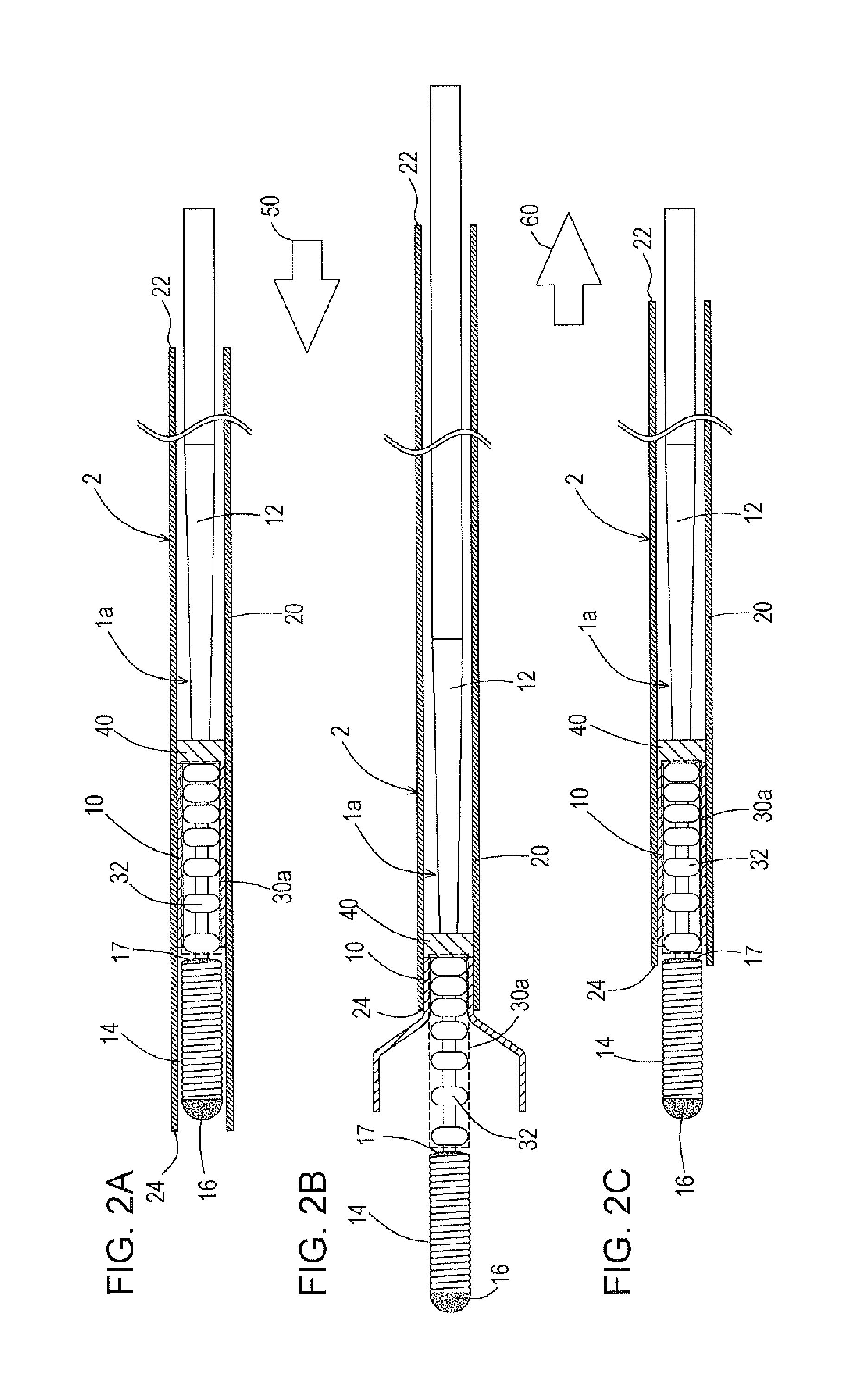
[0018]Referring first to FIGS. 1A to 1C, a pusher guide wire 1 of the disclosed embodiments will be described. In each of FIGS. 1A to 7C, the left side of each drawing corresponds to a distal end (a front end) of a catheter to be inserted into the body, and the right side of each drawing corresponds to a proximal end (a base end) of the catheter to be manipulated by a technician, such as a doctor.

[0019]As illustrated in FIGS. 1A to 1C, the pusher guide wire 1 for delivering a stent 10 to a target site includes a core shaft 12, a first coil body 14 (a distal end coil body) that covers a distal end portion of the core shaft 12, a first securing portion 16 that joins a distal end of the core shaft 12 and a distal end of the first coil body 14 to each other, a pusher portion 40 that is disposed on the proximal side (the right side in the drawing) with respect to the first coil body 14 and that is fixed to the core shaft 12, and a stent holding portion 30 that is disposed between the fir...


PUM


Abstract

A pusher guide wire for delivering a stent to a target site includes a core shaft, a coil body that covers a distal end portion of the core shaft, a pusher portion that is fixed to the core shaft at a position proximal to the coil body, and a stent holding portion that is fixed to the core shaft at a position between the coil body and the pusher portion. In the pusher guide wire, frictional resistance between the stent and the stent holding portion is larger at a proximal end portion of the stent holding portion than at a distal end portion of the stent holding portion.

Description

CROSS REFERENCE TO RELATED APPLICATION[0001]This application claims priority to Japanese Application No. 2014-207392 filed on Oct. 8, 2014, the content of which is incorporated by reference herein in its entirety.BACKGROUND OF THE INVENTION[0002]The disclosed embodiments relate to a medical device. Specifically, the disclosed embodiments relate to a pusher guide wire for delivering a stent housed in a catheter to a target site.[0003]A stent is a piece of medical equipment used to treat a stricture or a disorder that has developed in a blood vessel or a digestive organ. For example, a stent can be used to support a lumen of a blood vessel or a digestive organ that has been expanded from a constricted condition in order to prevent the blood vessel or the digestive organ from again becoming constricted, or can be used to confine an embolus coil within an aneurysm formed in an arterial blood vessel of the abdomen or the brain so that the aneurysm does not rupture.[0004]In general, a ste...

Claims


Application Information

Patent Timeline
Patent Type & Authority Applications(United States)
IPC IPC(8): A61F2/95
CPCA61F2002/9505A61F2/95A61F2/966A61F2002/9534A61F2002/9665A61F2250/0021A61F2250/0039
Inventor NISHIGISHI, MAKOTO
Owner ASAHI INTECC CO LTD
Why Eureka
Try Eureka