Friction controlled ball joint

a ball joint and friction control technology, applied in the field of ball joints, can solve the problems of significant variation in the dynamics of the system, negatively affecting the dynamic behavior of the mechanical system, and the friction in the ball joint is present, and achieves the effect of easy manufacturing and control of the friction in the ball join

Inactive Publication Date: 2014-06-17
HONDA MOTOR CO LTD
View PDF41 Cites 10 Cited by
  • Summary
  • Abstract
  • Description
  • Claims
  • Application Information

AI Technical Summary

Benefits of technology

[0010]One advantage of this invention is that the friction in a ball joint may be controlled.
[0011]Another advantage of this invention is that the friction in a ball joint may be controlled in different directions.
[0012]Another advantage of this invention is that the friction controlled ball joint may be easily manufactured.

Problems solved by technology

Friction exists in ball joints due to the inherent mechanical interference.
Excessive friction is a disadvantage in that it negatively influences the dynamic behavior of the mechanical system.
Moreover, mechanical friction of known ball joints degrades with time and, often of more concern, causes a significant variation in the dynamics of the system.

Method used


Image

  • Friction controlled ball joint
  • Friction controlled ball joint
  • Friction controlled ball joint

Examples


Embodiment Construction

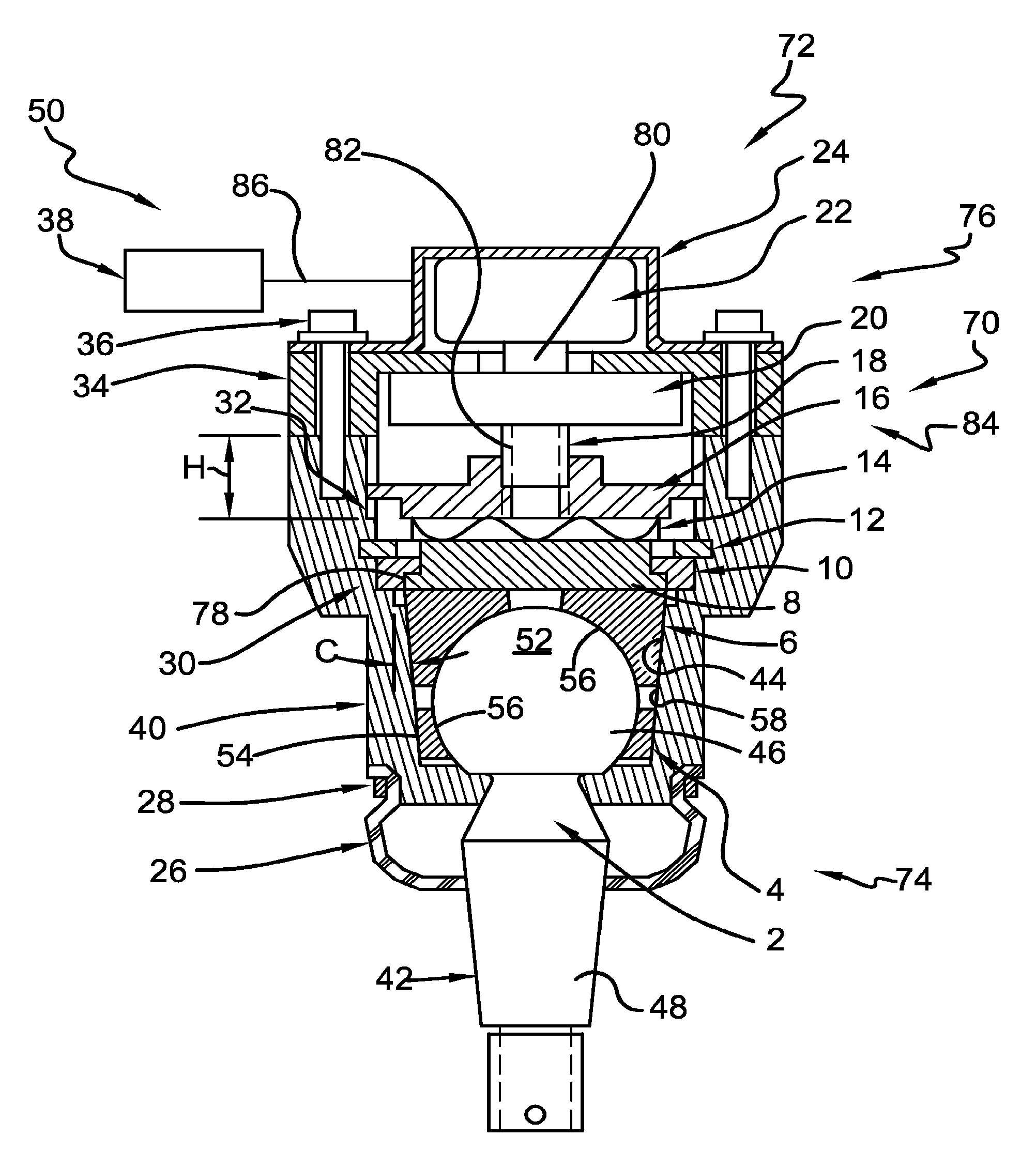
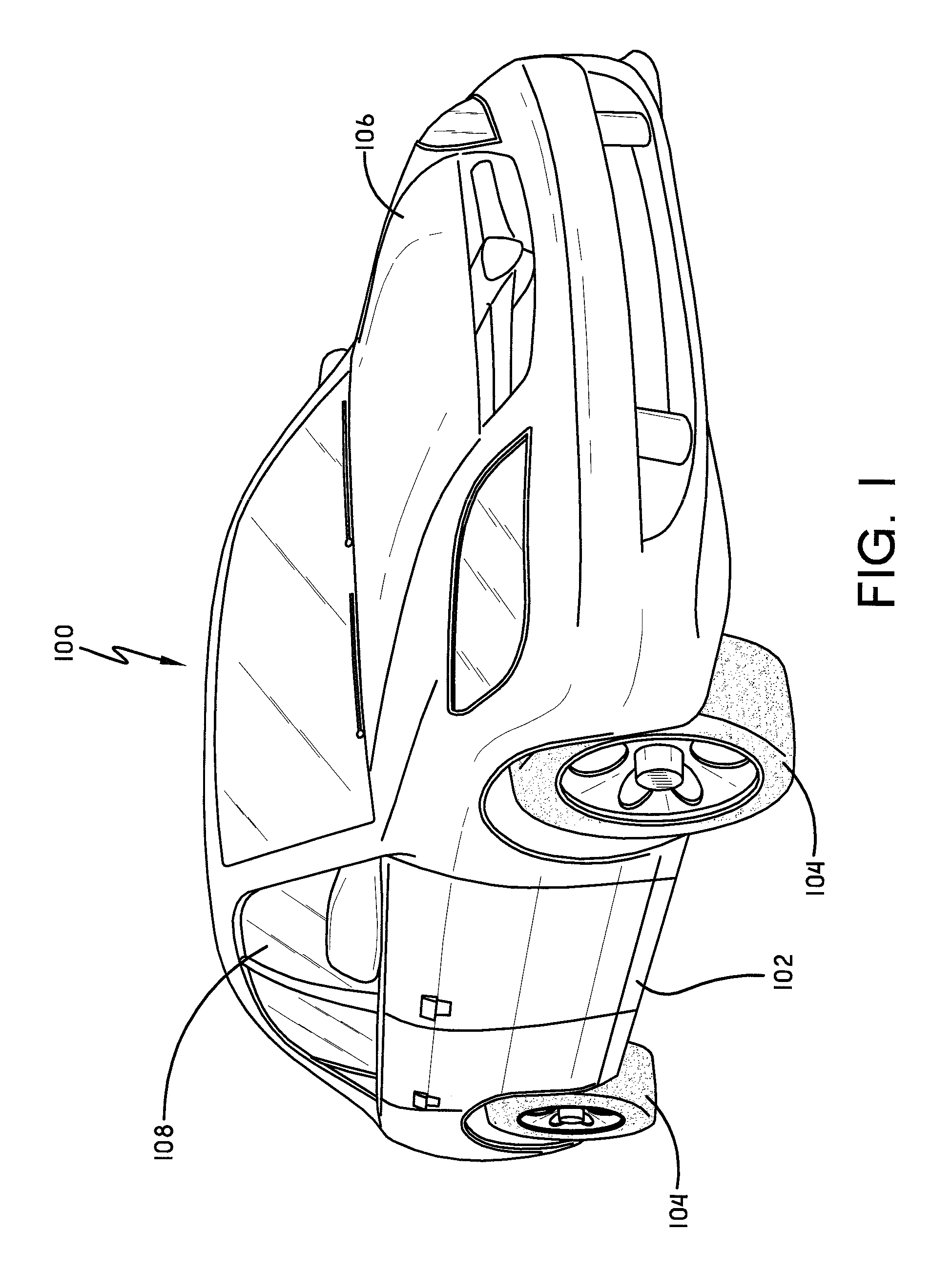
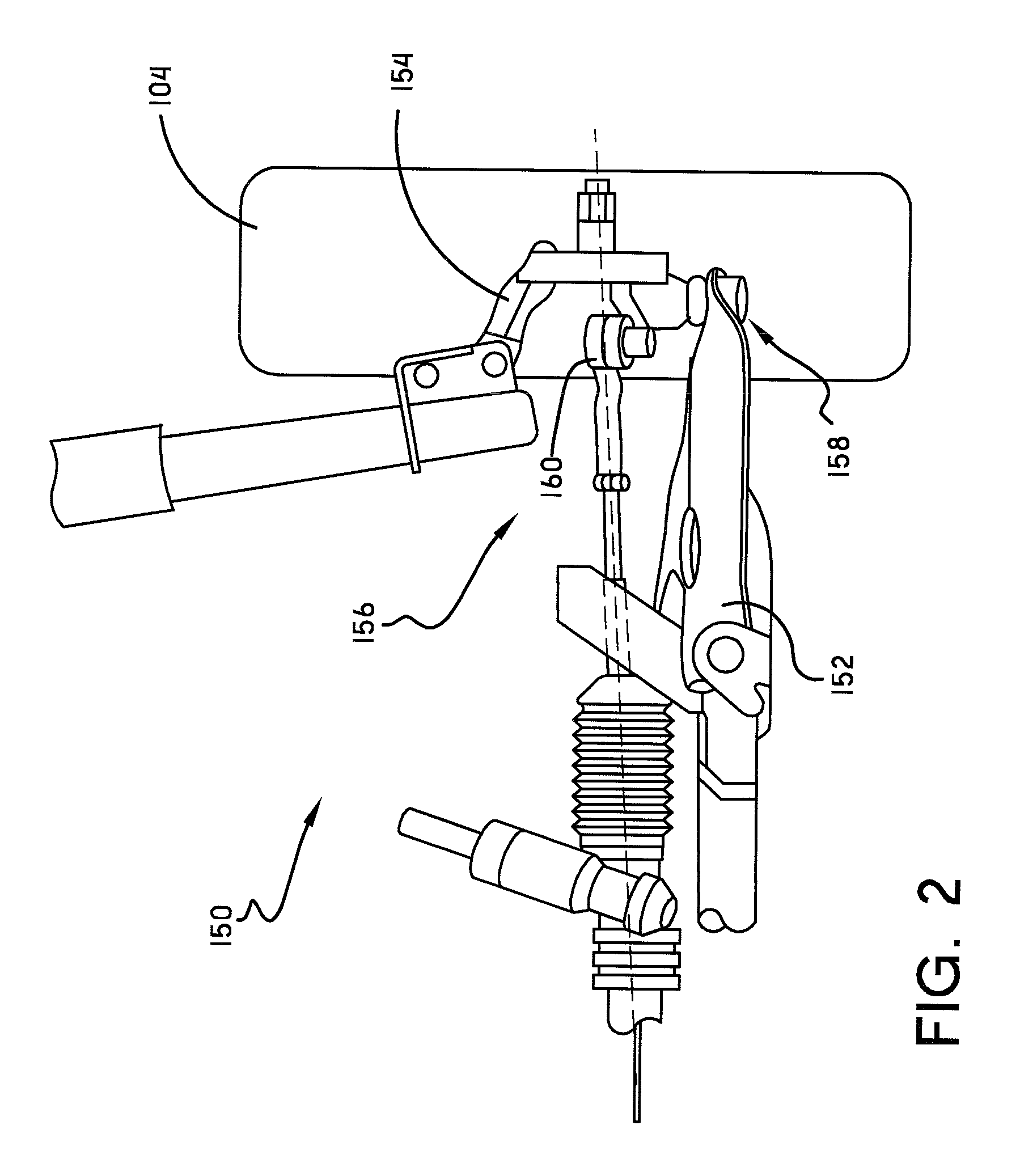
[0022]Referring now to the drawings wherein the showings are for purposes of illustrating embodiments of the invention only and not for purposes of limiting the same, and wherein like reference numerals are understood to refer to like components, FIG. 1 shows a vehicle 100 that may be equipped with one or more ball joint assemblies 50 used in a chassis system 150 according to this invention. However, it should be noted that this is an exemplary use only as this invention is not limited to uses with chassis systems or with vehicles. While the vehicle 100 shown is a sedan, it is to be understood that the ball joint assembly 50 of this invention may be used with any vehicle chosen with the sound judgment of a person of skill in the art including, for some non-limiting examples, cars, sports utility vehicles (SUVs), trucks, motorcycles, aircraft and agricultural machinery. The vehicle 100 may include a frame 102, one or more ground engaging wheels 104 mounted to the frame 102, and a loc...


PUM


Abstract

A ball joint assembly may include a housing having a cavity, a friction seat received within the cavity, and a ball stud having a ball that frictionally contacts the friction seat. In one embodiment, a friction control mechanism moves the friction seat within the cavity to adjust the friction between the ball and the friction seat. In another embodiment, both the cavity and an outer surface of the friction seat may be substantially frustoconically shaped.

Description

I. BACKGROUND[0001]A. Field of Invention[0002]This invention relates to the art of ball joints and more specifically to methods and apparatuses related to a friction controlled ball joint.[0003]B. Description of the Related Art[0004]It is well known to use ball joints in widely varied mechanical applications including automotive chassis systems, aircraft landing gear systems, and agricultural machinery. The fundamental function of a ball joint is to connect two mechanical parts together while allowing relative rotational movement of the parts. Friction exists in ball joints due to the inherent mechanical interference. Excessive friction is a disadvantage in that it negatively influences the dynamic behavior of the mechanical system. Moreover, mechanical friction of known ball joints degrades with time and, often of more concern, causes a significant variation in the dynamics of the system. Sometimes, however, friction in ball joints can be a positive characteristic helpful for dampi...

Claims


Application Information

Patent Timeline
Patent Type & Authority Patents(United States)
IPC IPC(8): F16C11/06F16C11/08
CPCF16C11/06F16C11/0647F16C11/0652Y10T403/32819Y10T403/32754Y10T403/32311
Inventor YU, JINGHONGWOLF, DAVIDVOGEL, DANIELHOSNI, EDWARD A.SAMALOT-QUILES, ANGEL D.
Owner HONDA MOTOR CO LTD
Why Eureka
Try Eureka