Adjustable support arm for a vehicle exterior rearview mirror assembly

a rearview mirror and support arm technology, applied in the direction of machine supports, instruments, other domestic objects, etc., can solve the problems of shaky and unusable mirror assemblies, limiting the ability to adjust the position of the mirror for viewing, and the range of positions of the swivel joints not offering a wide range of positions for positioning the mirror assembly

Inactive Publication Date: 2012-04-10
LANG MEKRA NORTH AMERICA LLC
View PDF26 Cites 15 Cited by
  • Summary
  • Abstract
  • Description
  • Claims
  • Application Information

AI Technical Summary

Benefits of technology

[0014]In a further embodiment, an upper conical pivot washer is carried between the tapered retainer flange and the conical bushing flange which is complementary in shape to the tapered retainer flange and the conical bushing flange for controlling frictional resistance of the sliding engagement between the tapered retainer flange and bushing.
[0017]In a further embodiment, the bushing includes an annular spring recess receiving the compression spring so that the bias from the compression spring is evenly distributed across the bushing.
[0019]In a further embodiment, a lower conical pivot washer is disposed between the tapered collar and the lower tapered pivot surface which is complementary in shape to the tapered collar and the lower tapered pivot surface for controlling frictional resistance of sliding engagement between the tapered collar and the lower tapered pivot surface.

Problems solved by technology

The swivel joints are typically designed using detent joints to hold the mirror in one of a few pre-defined operational or storage positions, highly limiting the ability to adjust the position of the mirror for viewing.
While providing some flexibility to position the mirror, such swivel joints do not offer a wide range of positions for positioning the mirror assembly.
Additionally, the detent systems known in the prior art suffer from significant wear and tear issues that loosen the detent resistance to secure the mirror assembly in the desired position, eventually leading to a shaky and unusable mirror assembly.
Most conventional mounting arrangements, including swivel joint arrangements, suffer from complicated constructions requiring, for instance, adapters, multiple piece connectors, multiple support braces, and a variety of screws, bolts and the like to attach the support arm to the vehicle.
Such complicated mounting arrangements are more cumbersome, costly and labor intensive than may be desired.
Perhaps more importantly, however, is the fact that many of these assemblies which utilize a multiplicity of connectors are subject to vibration resistance problems that result in loosening of the connections between the various mounting components of the mirror assembly, which leads to mirror shaking and visual impairment.
As noted above, a substantial problem with external vehicle rearview mirrors, particularly in the case of commercial vehicles, is the occurrence of vibration.
First, vibration can negatively affect the use of the mirror, and second, vibration of the mirror can lead to damage due to fatigue for nearly every component in the mirror assembly.
Over time, wear caused by wind and road vibrations loosens the connections between the various support members which mount the mirror assembly to the vehicle.
In many cases, after only minimal wear has occurred on most large mirror assemblies for commercial vehicles, excessive mirror shaking is present in the assembly that significantly reduces effective use of the mirror.
The support arms are particularly susceptible to wind and road vibrations due to the heavy loads of supporting the entire mirror assembly, often leading to premature failure and replacement of support member components if not properly installed on the vehicle.

Method used


Image

  • Adjustable support arm for a vehicle exterior rearview mirror assembly
  • Adjustable support arm for a vehicle exterior rearview mirror assembly
  • Adjustable support arm for a vehicle exterior rearview mirror assembly

Examples


Embodiment Construction

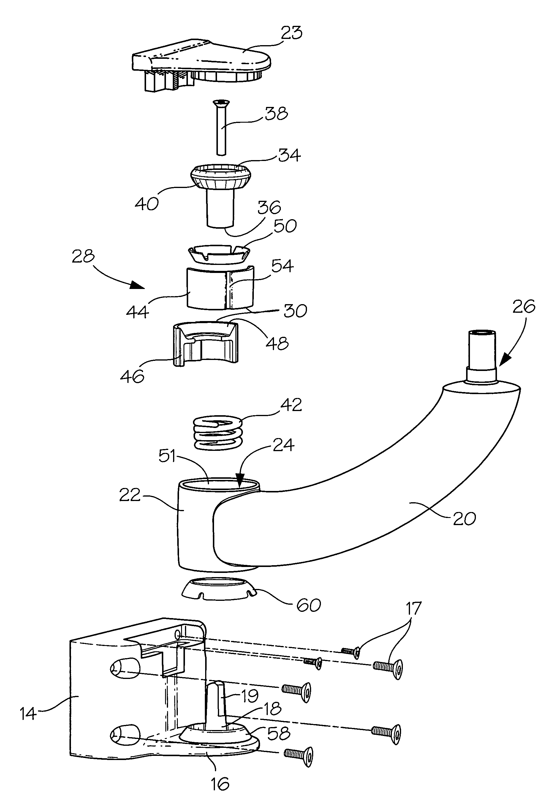
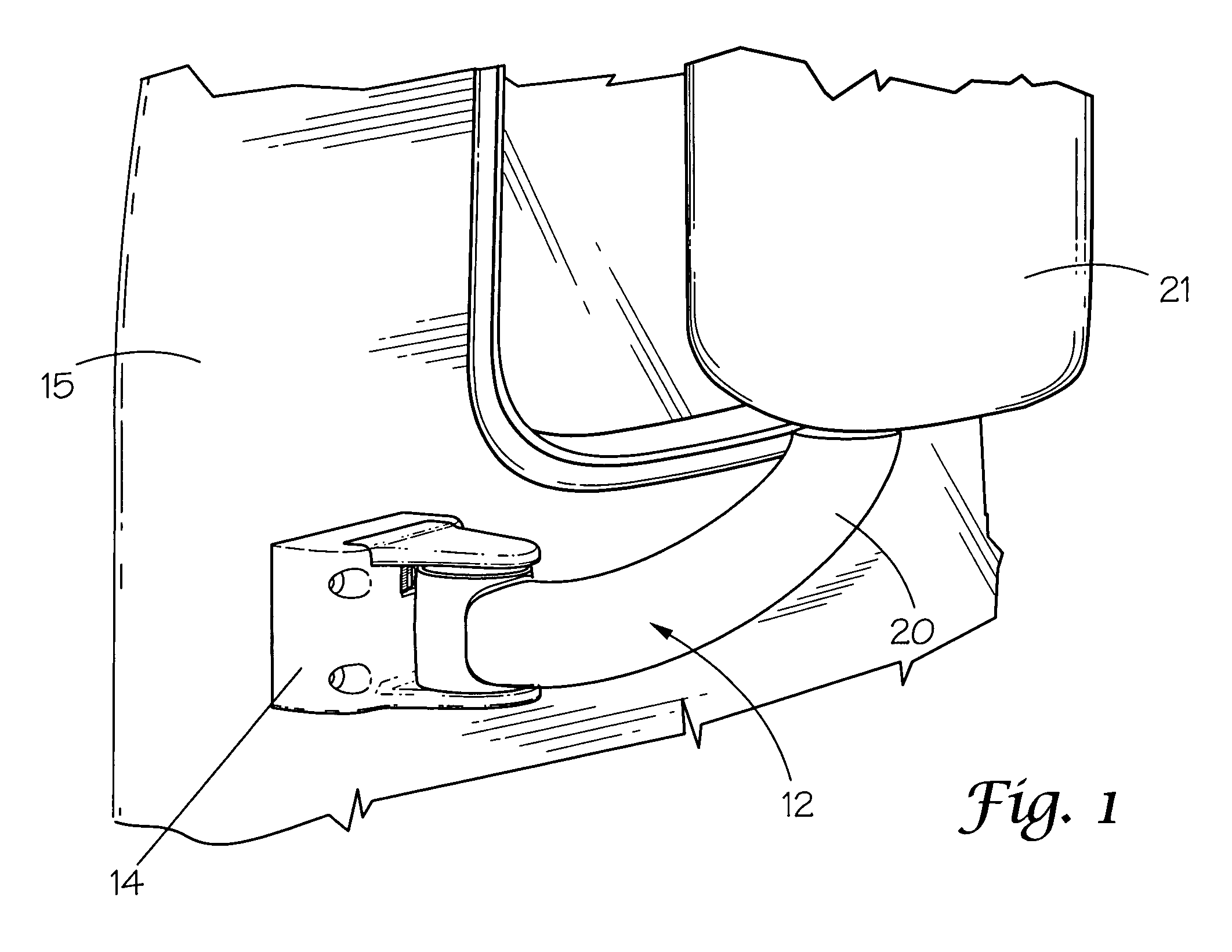
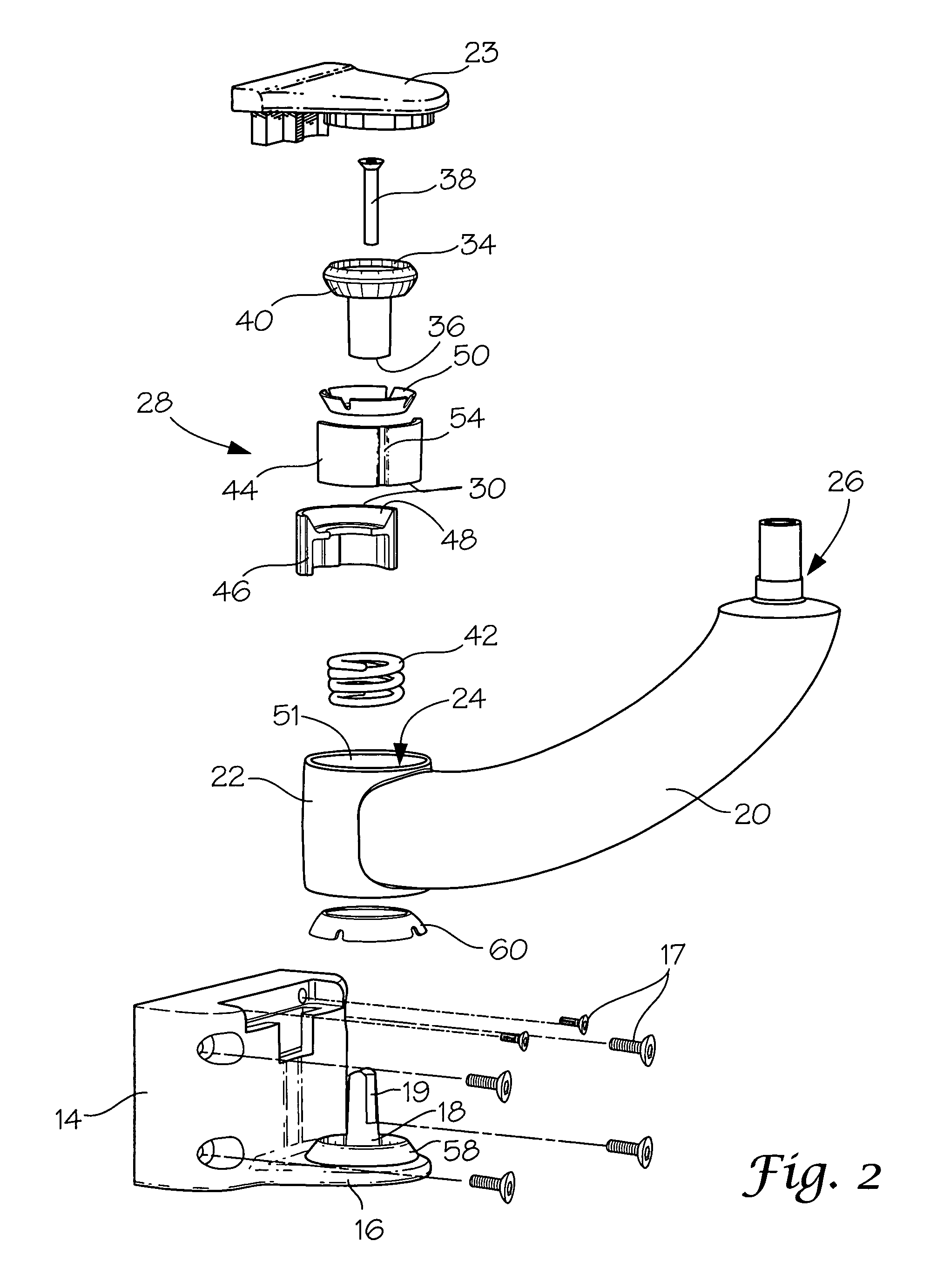
[0027]With reference to the drawings, the invention will now be described in more detail. Referring to FIG. 1, an adjustable support arm, designated generally as 12, is shown for a vehicle exterior rearview mirror assembly. As set forth herein below, adjustable support arm 12 includes a pivot control unit 28 (FIG. 2) which allows for variable positioning of a holder 20, which carries mirror head 21. Additionally, pivot control unit 28 is constructed and arranged to account for wear and tear between various friction fit components to maintain a minimum pivot resistance on the holder to prevent shaking and unwanted pivoting of holder 20.

[0028]Referring to FIGS. 1 and 2, adjustable support arm 12 includes a holder base 14 adapted for attaching to vehicle exterior 15. Holder base 14 is preferably bolted to vehicle exterior 15 using attachment members 17 so that there is no play between vehicle exterior 15 and holder base 14. Other well-known attachment methods to those skilled in the ar...


PUM


Abstract

An adjustable support arm for a vehicle exterior rearview mirror assembly comprising a holder base adapted for mounting to the vehicle; a holder pivotally carried on the holder base; a pivot control unit included in the holder for engaging the holder base to resist rotation of the holder on the holder base; the pivot control unit including: a compression spring disposed within a retainer opening of the holder; a bushing carried on the compression spring for engaging a bearing surface in the retainer opening; and, a retainer carried in the retainer opening and coupled to the holder base to retain the compression spring and the bushing in the retainer opening, wherein the retainer is constructed and arranged to direct the bushing laterally against the bearing surface and the compression spring biases the bushing against the retainer in sliding engagement to resist rotation of the holder on the holder base.

Description

CROSS REFERENCE TO RELATED APPLICATION[0001]This application claims priority from U.S. Provisional Application Ser. No. 60 / 926,915, filed Apr. 30, 2007.BACKGROUND OF THE INVENTION[0002]1) Field of the Invention[0003]The present invention relates generally to exterior rearview mirror assemblies for motor vehicles, and more particularly, to an adjustable support arm having a pivot control unit for resisting uncontrolled rotational movement of the support arm while allowing for infinitely variable position adjustment.[0004]2) Description of Related Art[0005]Rearview mirror assemblies for vehicles, particularly for commercial trucks, exist in a wide variety of shapes and sizes. These various mirror assemblies include many different arrangements for mounting the mirror assemblies on the vehicles. On large, commercial vehicles, such as trucks and buses, mirrors are often secured within mirror housings mounted on a support arm so as to extend the mirror out from the side of the vehicle the...

Claims


Application Information

Patent Timeline
Patent Type & Authority Patents(United States)
IPC IPC(8): A47F1/14A47G1/02A47F5/00A47G1/24B60R1/02G02B7/182
CPCB60R1/06B60R1/0605
Inventor BRANHAM, MICHAEL DEAN
Owner LANG MEKRA NORTH AMERICA LLC
Why Eureka
Try Eureka