
Emergency shelter

a technology for emergency shelters and shelters, applied in protective buildings/shelters, building types, construction, etc., can solve problems such as power outages, residents may be unable to stay in their homes, and homes are intact but without electricity

Inactive Publication Date: 2015-01-29
SHIELDS PROD
View PDF12 Cites 4 Cited by
  • Summary
  • Abstract
  • Description
  • Claims
  • Application Information

AI Technical Summary

Benefits of technology

The present invention provides a temporary shelter that can be used in emergency situations, such as natural disasters, to provide temporary housing for people. The shelter is designed to retain heat or cold without the need for external power or fuel. It can be assembled inside a home and provides comfort for people who would otherwise have to vacate their homes. The shelter can also help people reduce power consumption by reducing the temperature in their homes. It is affordable, easy to deploy, and can be used in both emergency and voluntary situations.

Problems solved by technology

Many situations, such as natural disasters, like floods, tornadoes, and hurricanes, result in power outages.
Often, power outages leave homes intact but without electricity to run heaters and / or air conditioners.
If the temperature in the area is sufficiently hot or sufficiently cold, residents may be unable to stay in their homes.
The power outage may last for days or even weeks.
Often, this results in a need for temporary and / or emergency housing.
Unfortunately, physical space is needed for such temporary and / or emergency housing.
This can be difficult when the power outage was caused by an event that devastated a large area.
Conventional solutions for providing temporary and / or emergency housing can be expensive to deploy.
Further, vacating homes leaves them vulnerable to looters.
In addition to unplanned power outages, some people may wish to reduce their power consumption voluntarily by reducing the temperature in their homes in cold weather, and / or increasing the temperature in their homes in hot weather.
However, if the house is too hot or too cold, it may be difficult to sleep.

Method used


Image

  • Emergency shelter
  • Emergency shelter
  • Emergency shelter

Examples


Embodiment Construction

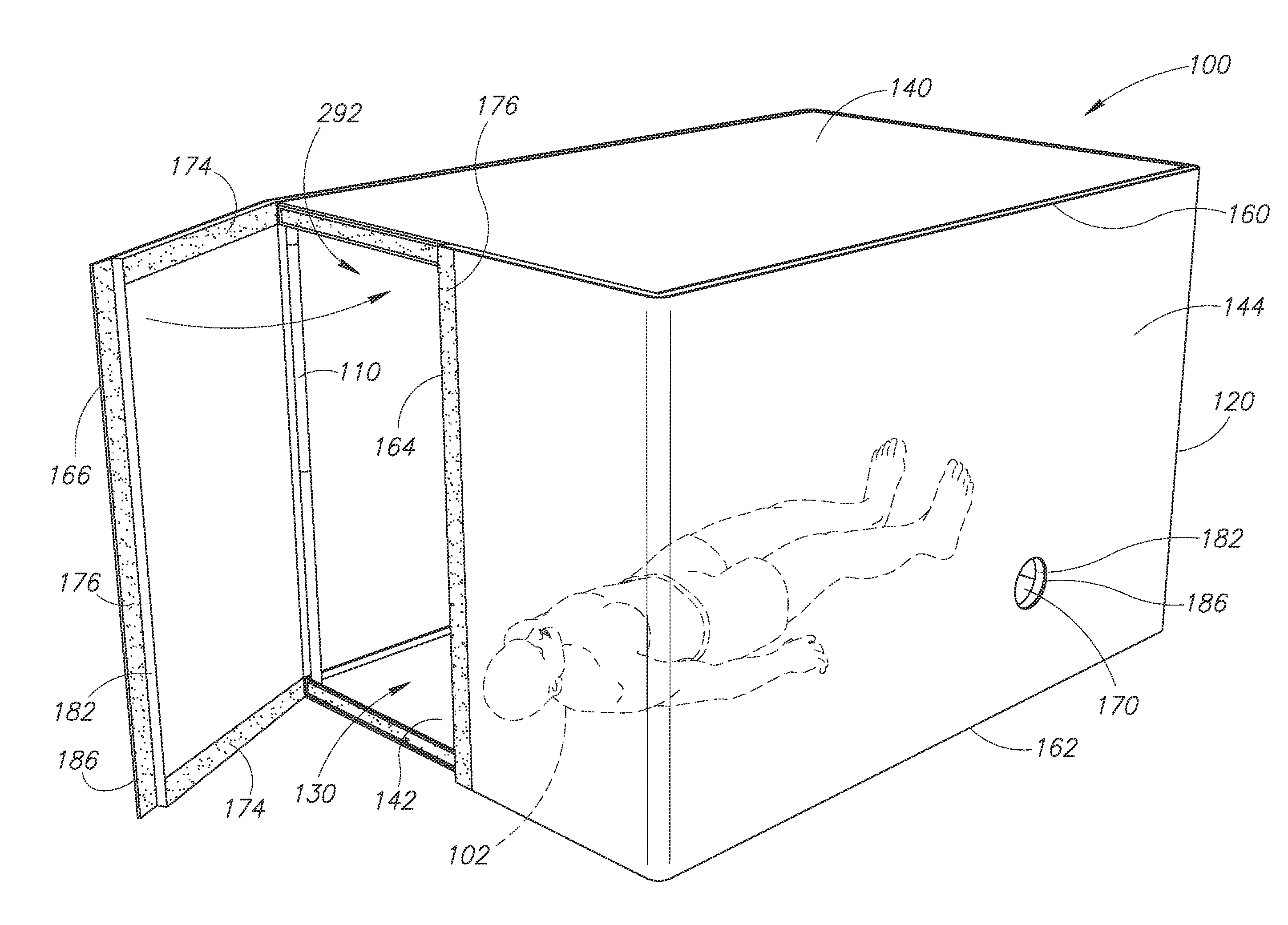
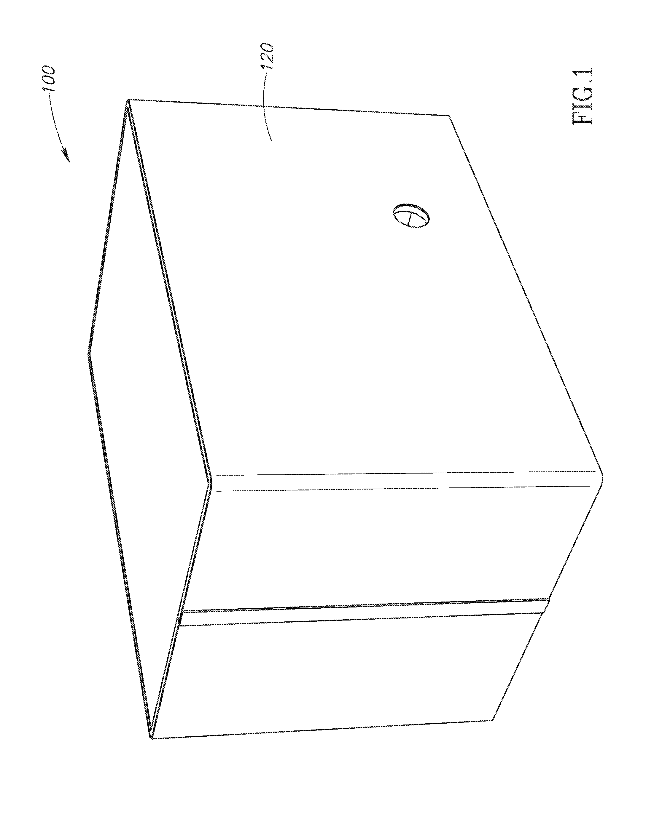
[0023]FIG. 1 is perspective view an emergency shelter 100. The shelter 100 is designed for indoor or outdoor use. For example, the shelter 100 may be assembled inside a home (e.g., on top of a bed, on a floor, and the like). The shelter 100 is configured to retain heat (e.g., body heat, heat generated by a chemical heating pack, and the like) or cold (e.g., cold generated by an ice pack) without the aid of external power or fuel (such as electricity, gas, oil, and the like).

[0024]Referring to FIG. 15, one or more people (e.g., a person 102) may assemble the shelter 100 inside a home and sleep comfortably inside the shelter when environmental temperatures inside the home would make doing so difficult, if not impossible. By using the shelter 100 in this manner, residents (e.g., the person 102) may avoid vacating the home during a power outage. In other words, the shelter 100 helps people stay in their homes when heating and / or cooling are not operating in the home.

[0025]The shelter 10...


PUM


Abstract

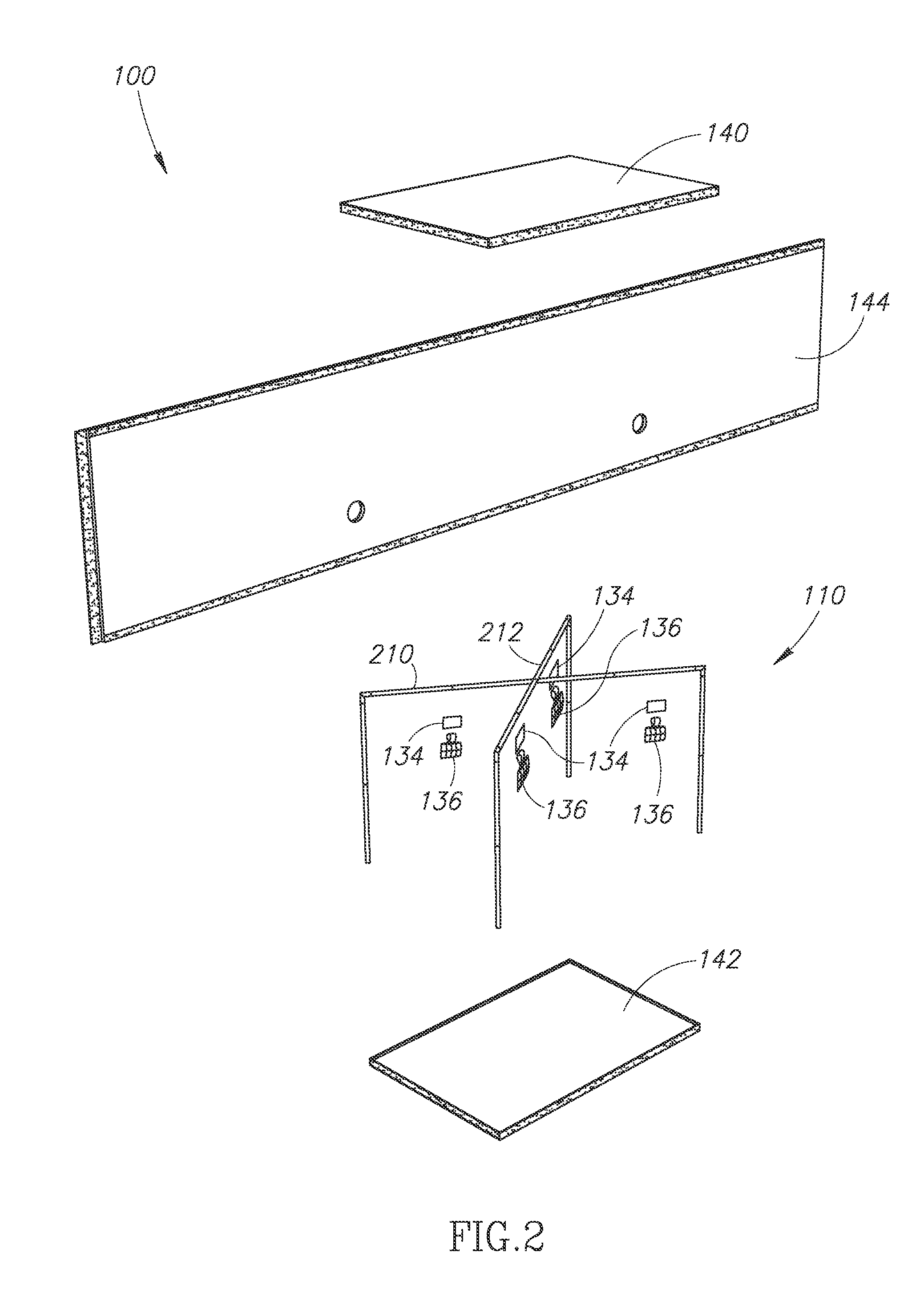
An emergency shelter including a support frame and an outer covering. The covering includes an upper panel positioned on top of the frame, and a side panel wrapped around the frame. The upper panel has at least one downwardly extending flap with one or more fasteners. The side panel has an upper edge portion with one or more fasteners removably fastened to the fastener(s) of the at least one downwardly extending flap. Optionally, a lower panel having at least one upwardly extending flap with one or more fasteners is positioned under the frame. The side panel may have a lower edge portion with one or more fasteners removably fastened to the fastener(s) of the at least one upwardly extending flap of the lower panel. One or more packs configured to change a temperature inside the shelter relative to a temperature outside the shelter may be placed inside the shelter.

Description

BACKGROUND OF THE INVENTION[0001]1. Field of the Invention[0002]The present invention is directed generally to temporary shelters used in emergency situations, such as natural disasters.[0003]2. Description of the Related Art[0004]Many situations, such as natural disasters, like floods, tornadoes, and hurricanes, result in power outages. Often, power outages leave homes intact but without electricity to run heaters and / or air conditioners. If the temperature in the area is sufficiently hot or sufficiently cold, residents may be unable to stay in their homes. The power outage may last for days or even weeks. Often, this results in a need for temporary and / or emergency housing.[0005]Unfortunately, physical space is needed for such temporary and / or emergency housing. This can be difficult when the power outage was caused by an event that devastated a large area. Conventional solutions for providing temporary and / or emergency housing can be expensive to deploy. Further, vacating homes l...

Claims


Application Information

Patent Timeline
Patent Type & Authority Applications(United States)
IPC IPC(8): E04H9/16
CPCE04H9/16E04H1/1205E04H1/125E04H15/10
Inventor THOMPSON, RICHARD LEE
Owner SHIELDS PROD
Learn More