Line clip and a spool of a spinning reel to which the line clip is mounted

a technology of spinning reel and line clip, which is applied in the direction of reels, applications, fishing, etc., can solve the problems of increasing the cost the likelihood of fishing line falling off the clip member, and the complexity of the line clip, so as to minimize the likelihood of fishing line being caught, the effect of minimizing the likelihood of fishing line being lost and cost effective and simple configuration

Active Publication Date: 2015-01-29
SHIMANO INC
View PDF11 Cites 10 Cited by
  • Summary
  • Abstract
  • Description
  • Claims
  • Application Information

AI Technical Summary

Benefits of technology

[0025]The skirt section can have a sheet member disposed in at least one part and can have a recess for mounting the line clip. In this case, the protrusion amount of the clip member from the outer peripheral surface of the skirt section is small, minimizing the likelihood that slacked fishing line will be caught by the clip member.
[0026]The recess comprises an opening through which the mounting member of the line clip can pass. In this case, since the mounting member can be mounted to the spool body in the skirt. the clip memb

Problems solved by technology

Specifically, when mounting a wide fishing line, the fishing line is more likely to fall off the clip member.
However, i

Method used


Image

  • Line clip and a spool of a spinning reel to which the line clip is mounted
  • Line clip and a spool of a spinning reel to which the line clip is mounted
  • Line clip and a spool of a spinning reel to which the line clip is mounted

Examples


first embodiment

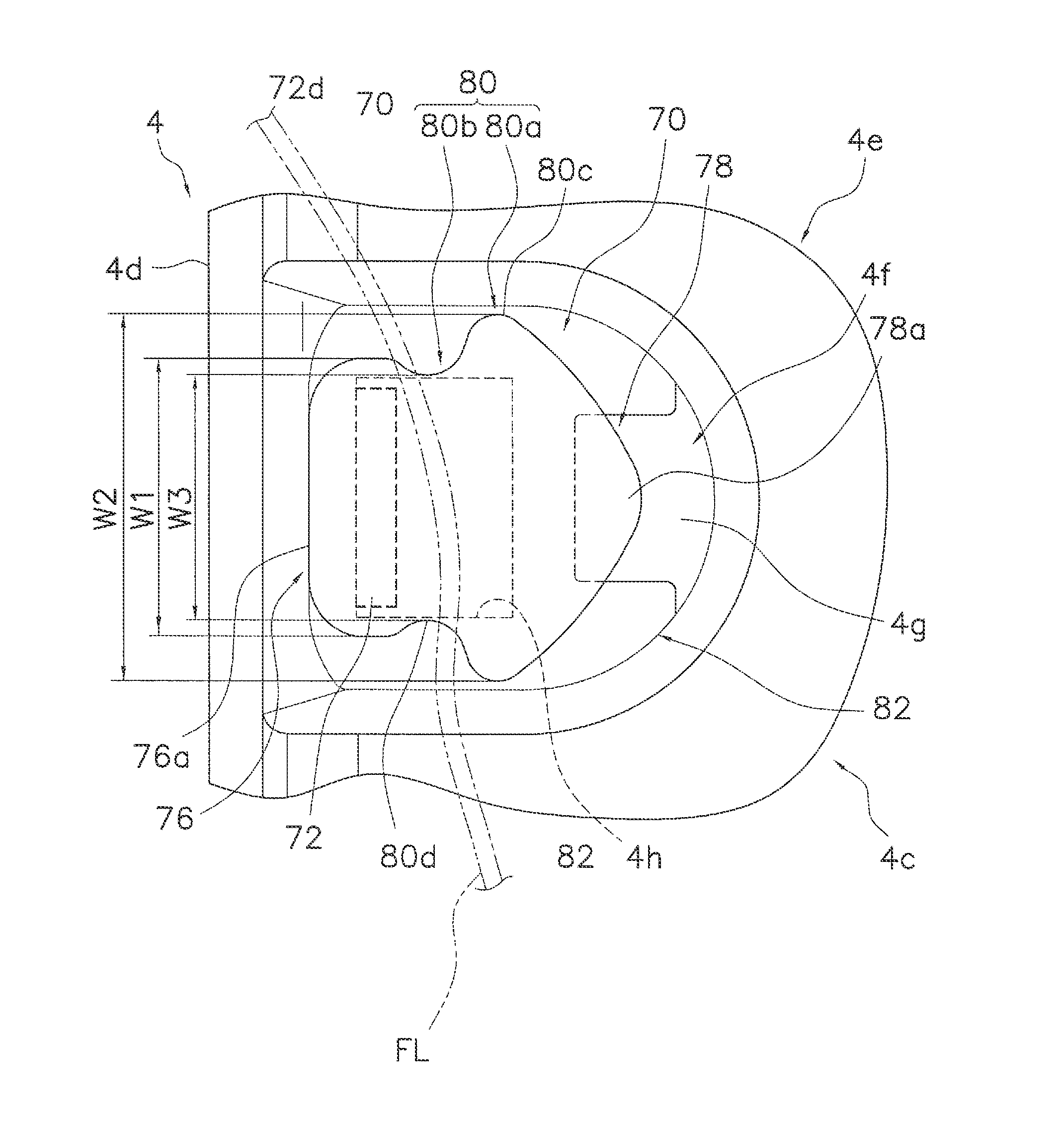
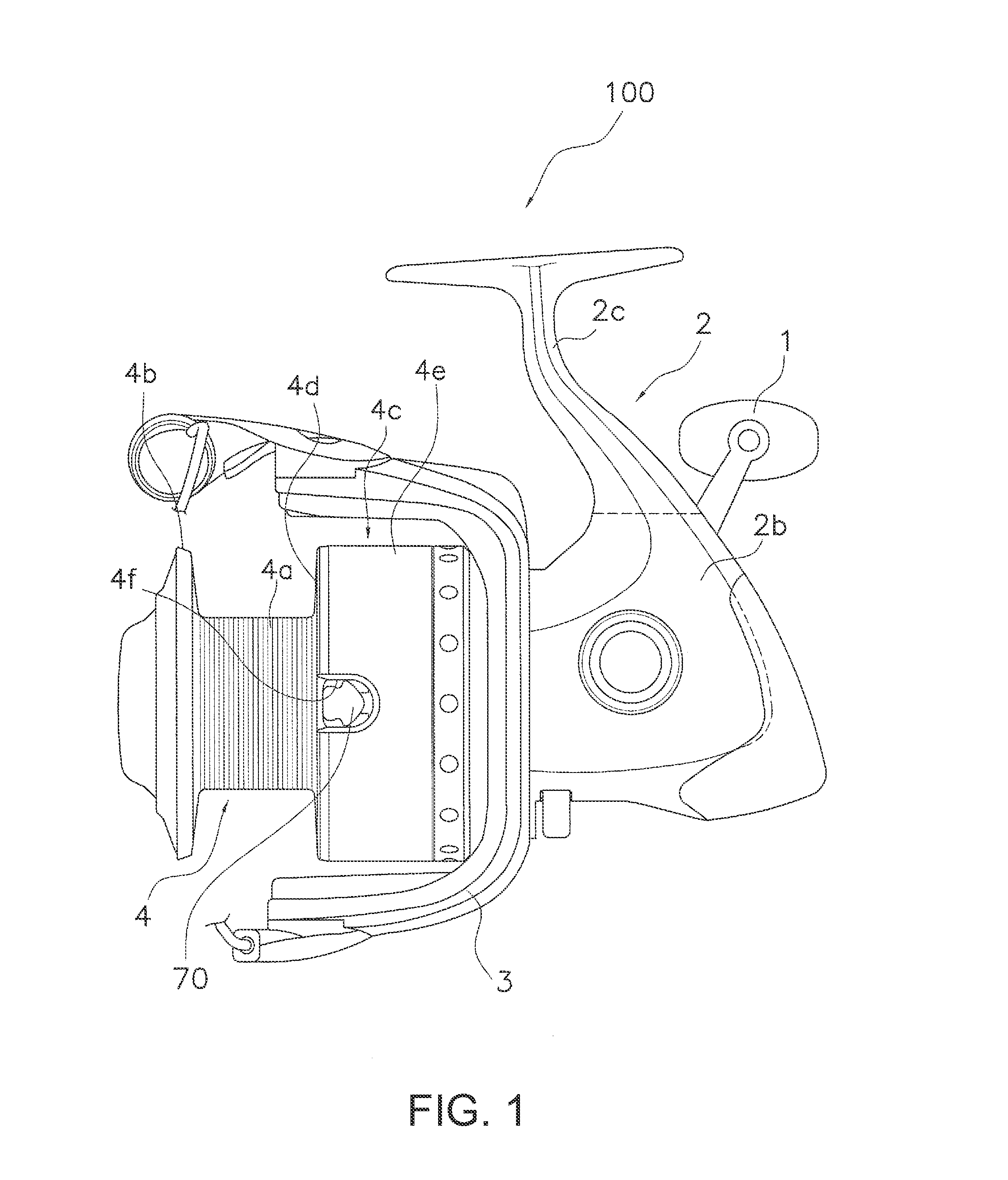
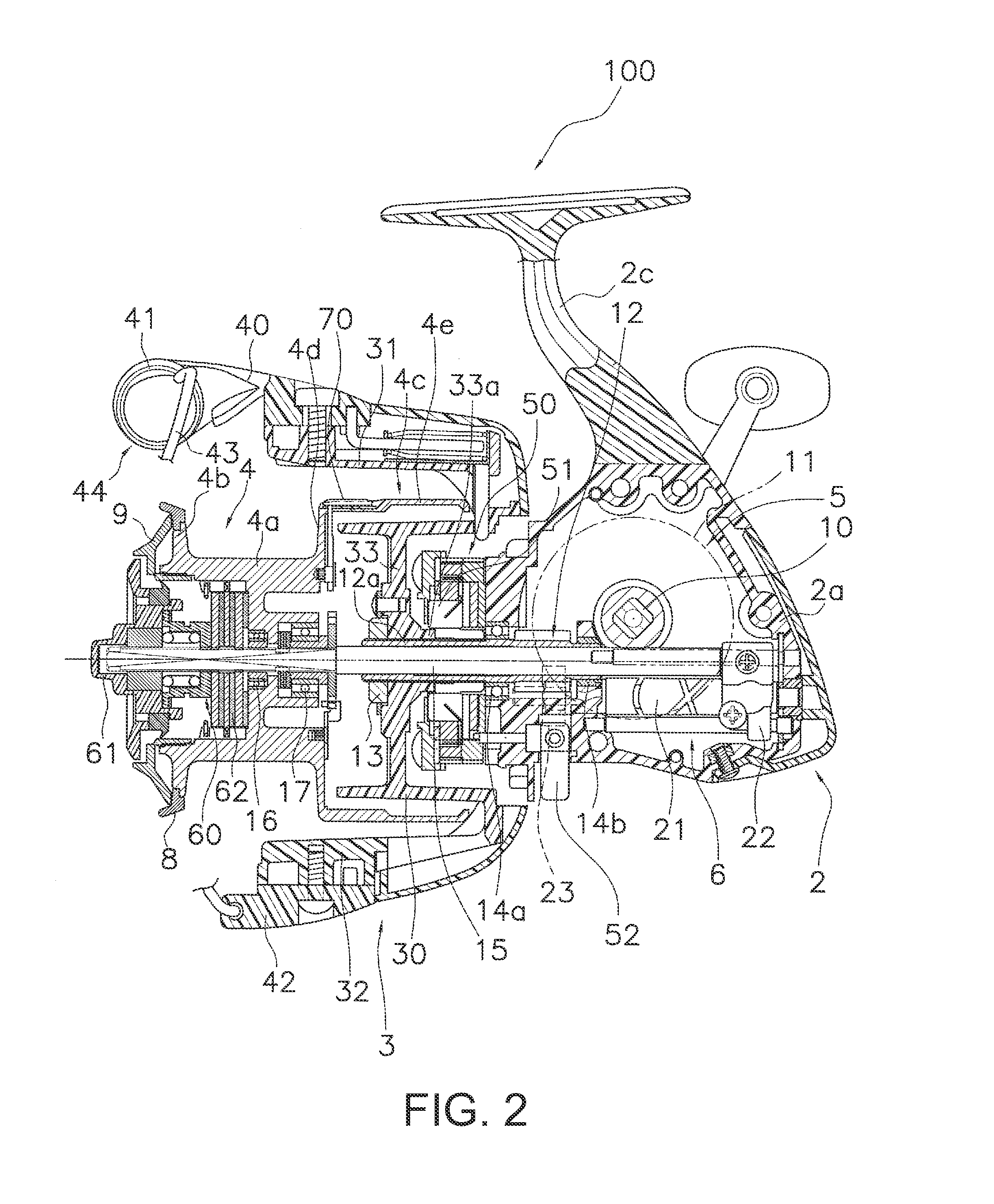
[0036]The spinning reel 100 employing the first embodiment of the present invention, as shown in FIG. 1, comprises a reel main body 2 that rotatably supports a handle 1, a rotor 3, and a spool 4. The rotor 3 is used for winding the fishing line onto the spool 4 and is rotatably supported by the front part of the reel main body 2. The spool 4 is used to wind the fishing line onto the outer peripheral surface and is disposed in order to be movable to the front and back of the front part of the rotor 3. Meanwhile, the handle 1 can be attached to either the left side or the right side of the reel main body 2. Here, when fishing and referring to the front and the back, the front refers to the direction in which the fishing line is unreeled, and the opposite direction is referred to as the back. Additionally, the left and right refer the left and right when looking at the spinning reel 100 from the rear.

[0037]The reel main body 2, as shown in FIG. 1 and FIG. 2, comprises a reel body 2a t...

second embodiment

[0059]In the line clip 70 of the first embodiment, the movement restriction portion 80 comprises a projection section 80a and a constricted section 80b, but in the line clip 270 of the second embodiment shown in FIG. 7, this section only comprises a projection section 280a that has a maximum width section 280c with a second width W2 that is wider than the first width W1. The other configurations are the same as those in the first embodiment, so the same reference symbols have be given in FIG. 7 and the explanations thereof have been omitted. In this kind of second embodiment, since there is no constricted section, the fishing line is more likely to move to the introduction end portion 78 side than the line clip 70 of the first embodiment. However, since there is no constricted section, the fishing line FL is less likely to come off with an even more cost effective and simpler configuration.

third embodiment

[0060]In the line clip 70 of the first embodiment, the movement restriction portion 80 comprises a projection section 80a and a constricted section 80b, but in the line clip 370 of the third embodiment shown in FIG. 8, the movement restriction portion 380 only comprises a constricted section 380b that has a third width W3 that is narrower than the first width W1. The other configurations are the same as those in the first embodiment, so the same reference symbols have be given in FIG. 8 and the explanations thereof have been omitted. In the third embodiment, since there is no projection section, the fishing line is more likely to move to the introduction end portion 78 side than the line clip 70 of the first embodiment. However, since there is no projection section, the fishing line FL is less likely to come off with an even more cost effective and simpler configuration.

Other Embodiments

[0061]One embodiment of the present invention was described above, but the present invention is n...


PUM


Abstract

A line clip of a spinning reel includes a mounting member and a clip member. The mounting member is configured to be mounted to the spool. The clip member is disposed on the mounting member, and is configured to lock the fishing line between the clip member and the surface of the spool. The clip member comprises a mounting end portion having the mounting member attached thereto, the mounting end portion having a predefined width in a circumferential direction of the spool, an introduction end portion configured to have a fishing line introduced thereto, and a movement restriction portion disposed between the mounting end portion and the introduction end portion, having a width that is different from the predefined width, and being configured to restrict the fishing line from moving to the introduction section side.

Description

CROSS-REFERENCE TO RELATED APPLICATIONS[0001]This application claims priority to Japanese Patent Application No. 2013-155769, filed on Jul. 26, 2013. The entire disclosure of Japanese Patent Application No. 2013-155769 is hereby incorporated herein by reference.BACKGROUND[0002]1. Field of Invention[0003]The present invention relates to a spool of a spinning reel and to a line clip that is mounted on the spool of the spinning reel.[0004]2. Background Information[0005]In a conventional spinning reel, a spool of the spinning reel reciprocates back and forth according to the rotation of the reel. The spool of spinning reel has a spool body, a front flange section, and a skirt section. A line clip for holding a fishing line that is mound to the skirt section of the spool of the spinning reel.[0006]This kind of line clip locks the end part of the fishing line that is wound on the spool body and functions to maintain a state in which the fishing line is wound to the spool body.[0007]The li...

Claims


Application Information

Patent Timeline
IPC IPC(8): A01K89/01
CPCA01K89/0111
Inventor HIRAOKA, HIROKAZUMATSUO, SHINGO
Owner SHIMANO INC
Why Eureka
Try Eureka