Eureka AIR delivers breakthrough ideas for toughest innovation challenges, trusted by R&D personnel around the world.

Assembly and method for assembling a cable puller

Inactive Publication Date: 2015-01-29
DUGGER DARRELL D
View PDF2 Cites 0 Cited by
  • Summary
  • Abstract
  • Description
  • Claims
  • Application Information

AI Technical Summary

Benefits of technology

The patent describes a cable puller assembly that includes a gripping assembly, a cable support member, and a pulling member. The assembly has an interior surface with friction elements to guide the cable through its channel. The method involves attaching the gripping assembly to a cable support member and then adding the pulling member. The technical effect of this patent is to provide a versatile and efficient way to pull cables that reduces the risk of damage to the cable during the process.

Problems solved by technology

In some applications, a cable puller may be used to couple a cable to a pulling device (e.g., a crane, winch, etc.) when directly coupling the device to the cable may be undesirable.
For example, pulling a steel cable using a crane may risk damage to the cable.

Method used


Image

  • Assembly and method for assembling a cable puller
  • Assembly and method for assembling a cable puller
  • Assembly and method for assembling a cable puller

Examples


Embodiment Construction

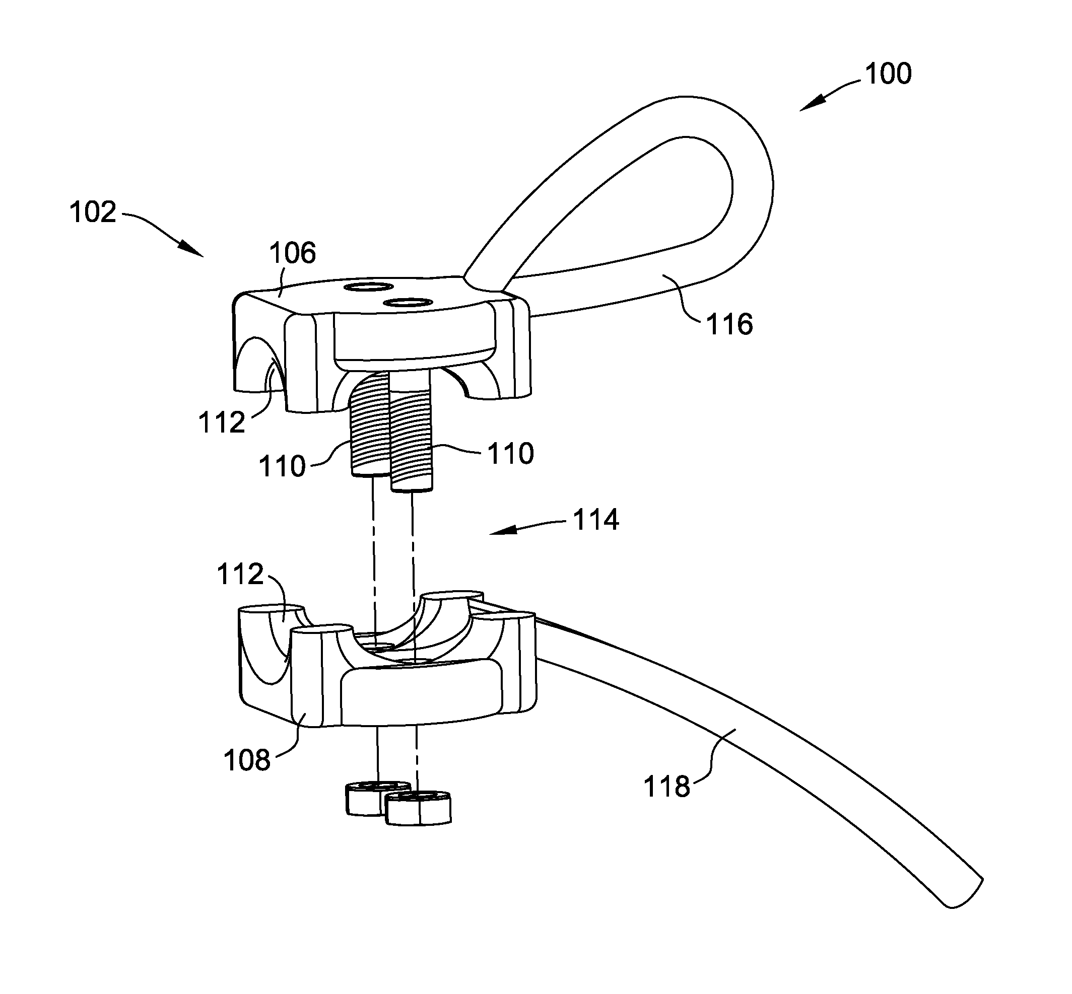
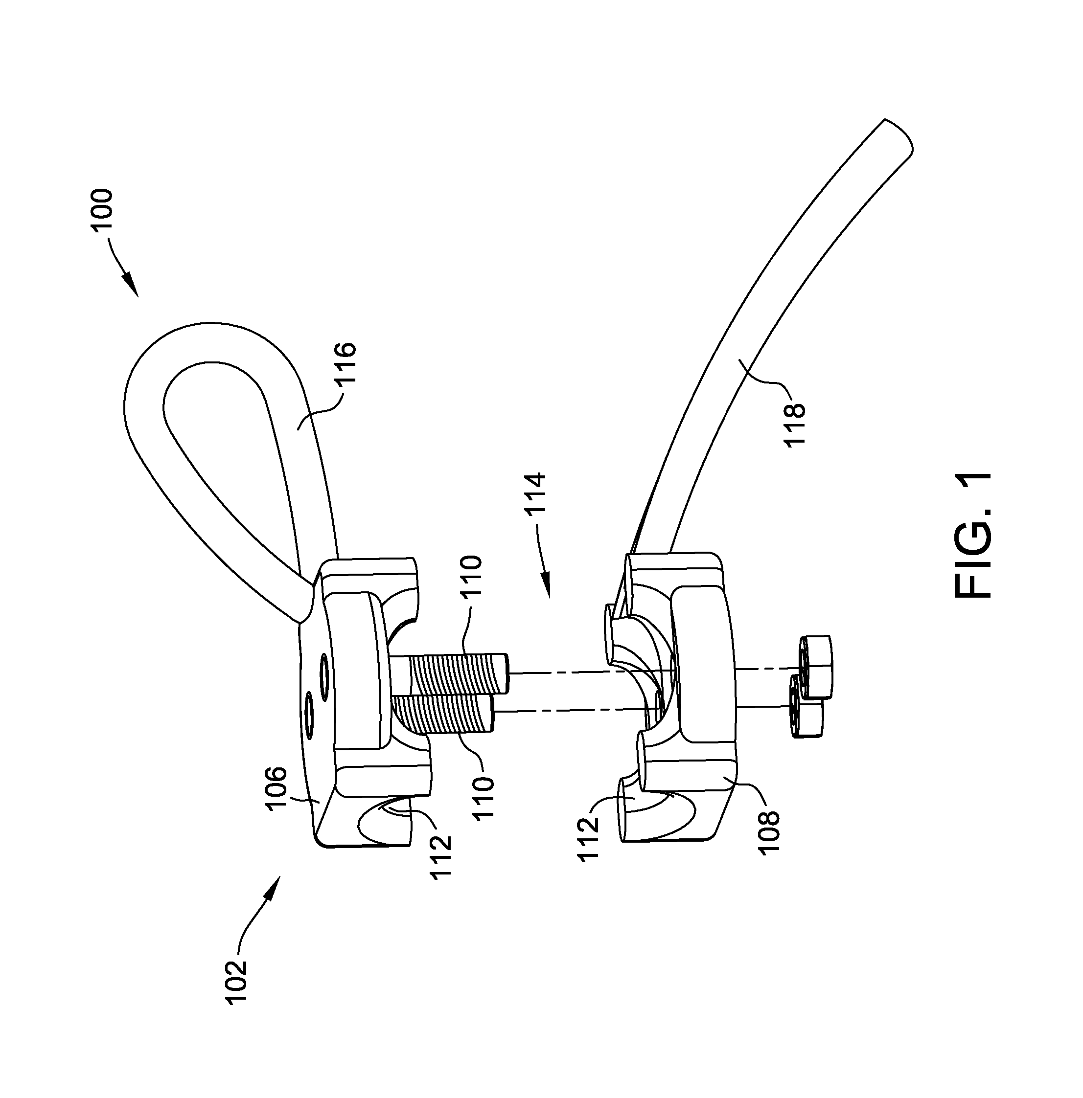
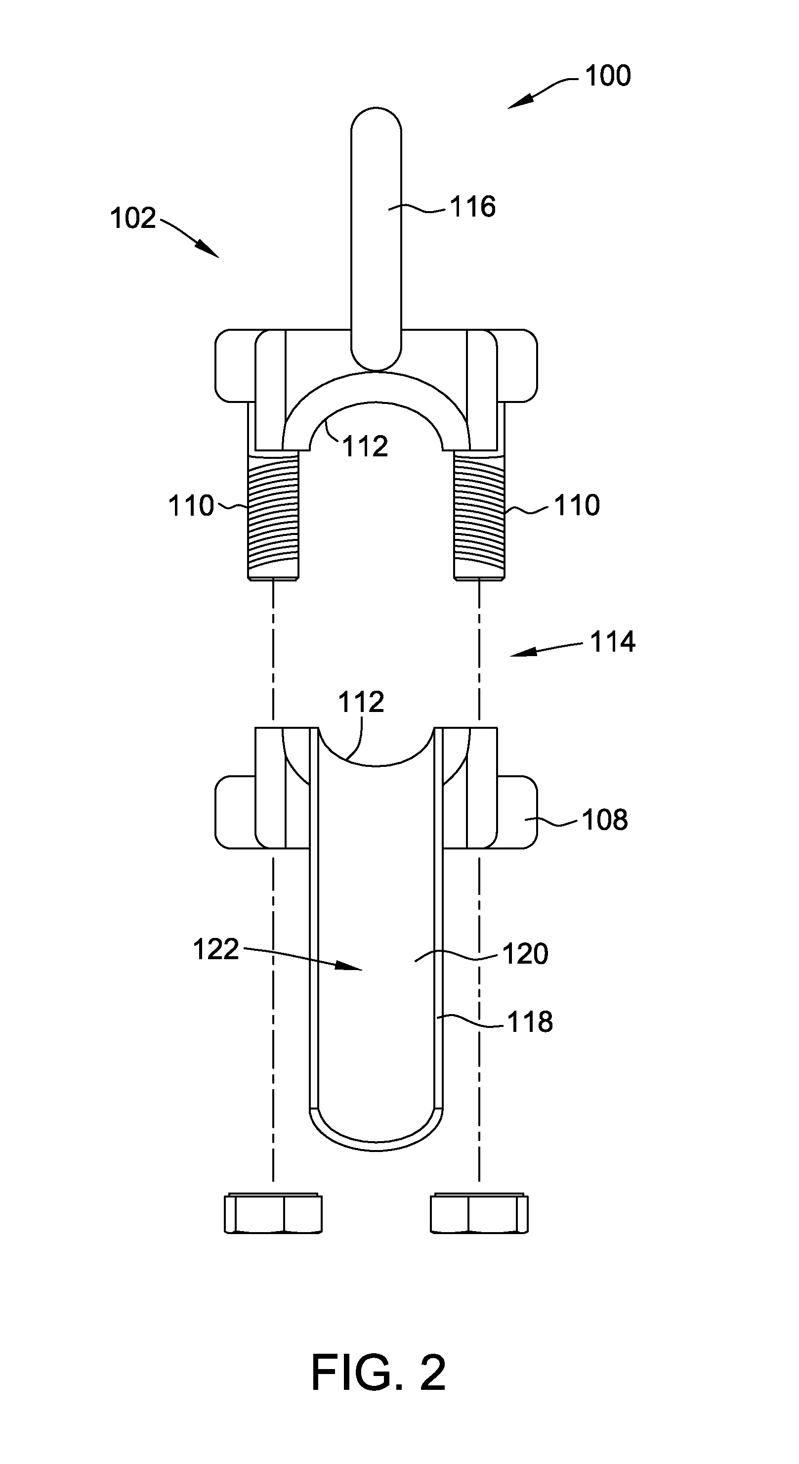
[0011]FIG. 1 is a perspective view of a cable puller assembly 100 in accordance with one embodiment of the disclosure. FIG. 2 is a front view of cable puller assembly 100 shown in FIG. 1. Cable puller assembly 100 includes a gripping assembly 102 configured to couple cable puller assembly 100 with a cable 104 (shown in FIG. 5). Gripping assembly 102 includes a first engaging member 106 removably coupled to a second engaging member 108 using at least one threaded connector 110. Gripping assembly 102 also includes an assembly interior surface 112 which at least partially defines a cable channel 114 configured to receive cable 104. In the exemplary embodiment, cable channel 114 is a substantially cylindrical channel that extends through gripping assembly 102. Assembly interior surface 112 is configured such that a width of cable channel 114 is substantially similar to a width of cable 104. Alternatively, assembly interior surface 112 is configured such that a width of cable channel 114...


PUM


Abstract

A cable puller assembly is provided. The cable puller assembly includes a gripping assembly including a first engaging member and a second engaging member removably coupled to the first engaging member, the gripping assembly further including an assembly interior surface at least partially defining a cable channel configured to receive a cable. The cable puller assembly further includes a plurality of friction elements disposed on the assembly interior surface, a cable support member coupled to the gripping assembly, the cable support member configured to guide the cable through the cable channel, and a pulling member coupled to the gripping assembly.

Description

BACKGROUND OF THE DISCLOSURE[0001]The field of the disclosure relates generally to a cable puller and, more specifically, to a cable puller that reduces the risk of damage to a cable during use.[0002]In some applications, a cable puller may be used to couple a cable to a pulling device (e.g., a crane, winch, etc.) when directly coupling the device to the cable may be undesirable. For example, pulling a steel cable using a crane may risk damage to the cable.BRIEF DESCRIPTION OF THE DISCLOSURE[0003]In one aspect, a cable puller assembly is provided. The cable puller assembly includes a gripping assembly including a first engaging member and a second engaging member removably coupled to the first engaging member, the gripping assembly further including an assembly interior surface at least partially defining a cable channel configured to receive a cable. The cable puller assembly further includes a plurality of friction elements disposed on the assembly interior surface, a cable suppor...

Claims


Application Information

Patent Timeline
IPC IPC(8): H02G1/08
CPCH02G1/08H02G1/081
Inventor DUGGER, DARRELL D.
Owner DUGGER DARRELL D
Why Eureka
Eureka Blog
Learn More