Eureka AIR delivers breakthrough ideas for toughest innovation challenges, trusted by R&D personnel around the world.

Vehicle operating device

Active Publication Date: 2015-02-05
ALPS ALPINE CO LTD
View PDF0 Cites 1 Cited by
  • Summary
  • Abstract
  • Description
  • Claims
  • Application Information

AI Technical Summary

Benefits of technology

The vehicle operating device described in this patent text includes several components that work together to improve the user experience. A control lever is rotated to an operating position using a rotation member and a rotation force. When the control lever is in the operating position, it is temporarily fixed using a temporary fixing mechanism. A cancelling drive member is movable and can be activated to move from a retreat position to a protruding position and cancel the operation. A deflectable spring member is used to move the cancelling drive member to the protruding position when activated. An advance / retreat control cam moves the cancelling drive member to the retreat position when the control lever is at the neutral position and moves it to the protruding position when the lever is at the operating position. An intermediate member is used to transfer the rotational force generated by the cancelling drive member to the control lever. An elastic member is used to push the intermediate member back to its initial position when the rotational force is applied. This device helps improve the feel and control of the vehicle's operating lever.

Problems solved by technology

Since the space in which the helical compression spring is disposed is required, a large height of a mechanism is required and, thus, it is difficult to make the turn signal switch device low-profile.
As a result, the drive load occurring when the cancel lever is retreated becomes excessive.
Accordingly, a large space for disposing the cancel lever and its operation space is needed between the cancel protrusion of the steering and the cancel lever and, thus, it is difficult to reduce the size of the turn signal switch device.

Method used


Image

  • Vehicle operating device
  • Vehicle operating device
  • Vehicle operating device

Examples


Embodiment Construction

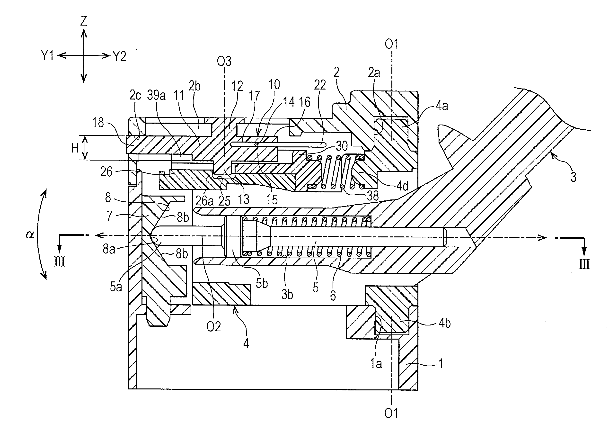
[0023]A vehicle operating device according to an exemplary embodiment of the present invention is provided on the side of a steering shaft. The vehicle operating device is used to activate a turn signal.

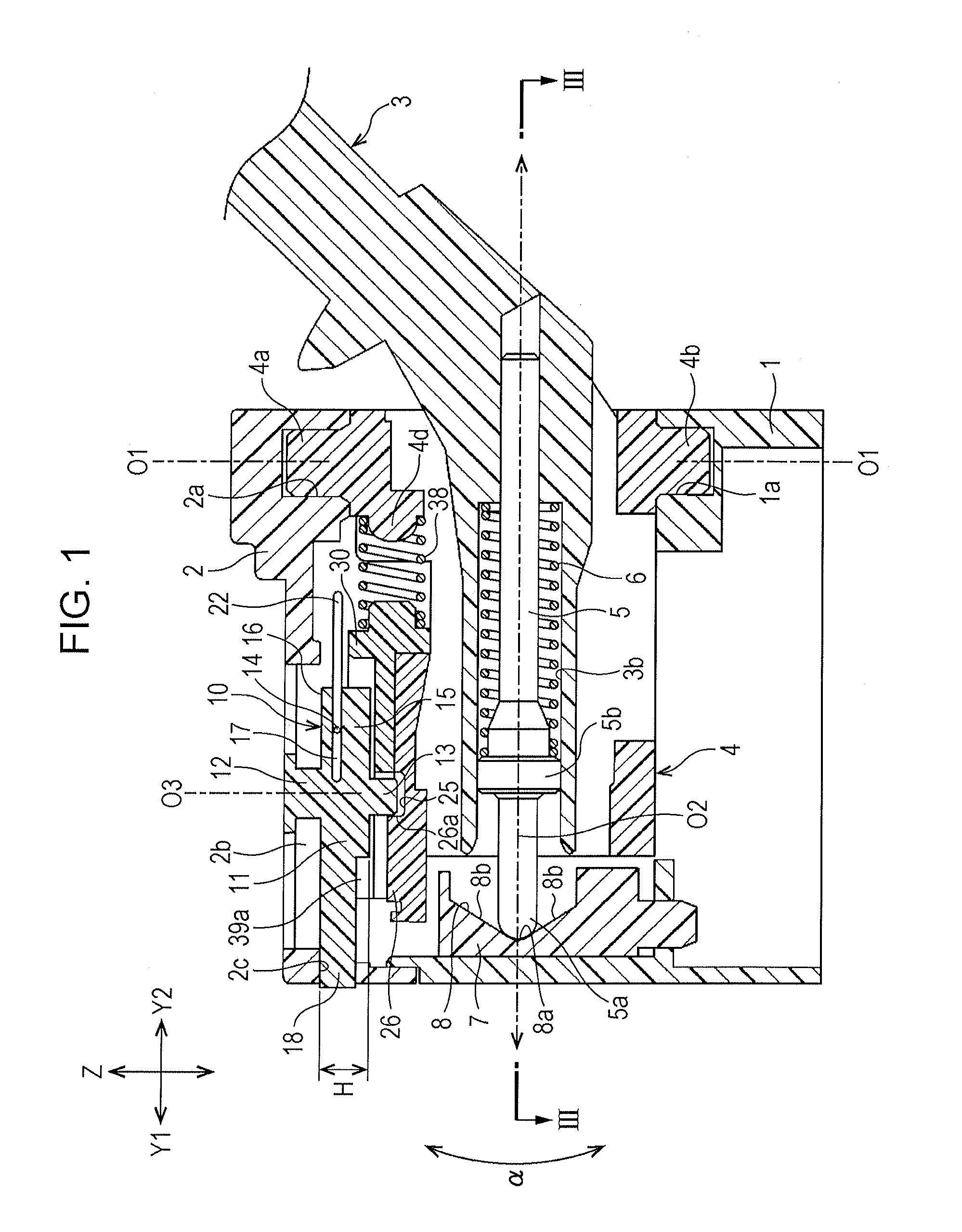
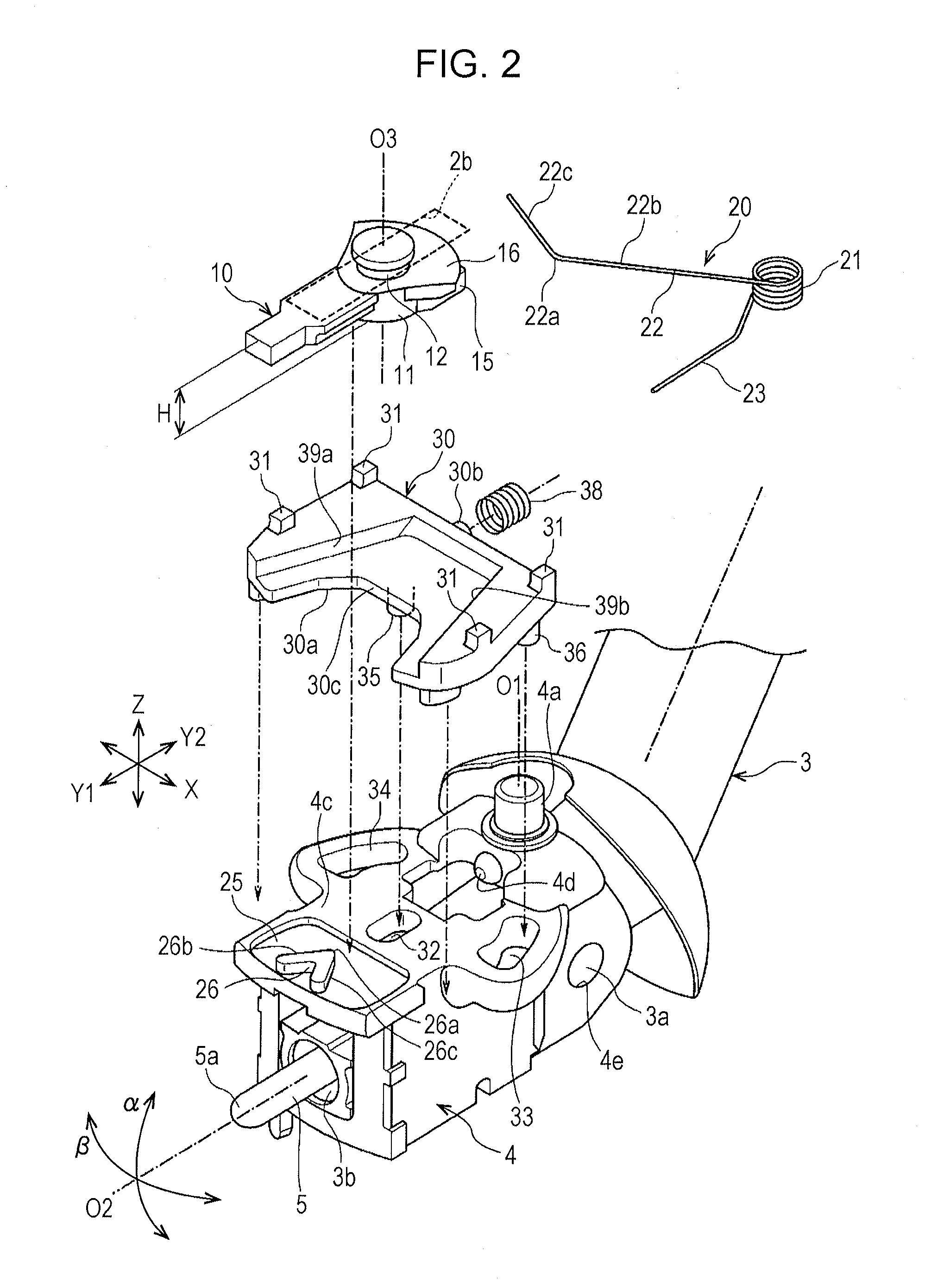
[0024]As illustrated in FIG. 1, the vehicle operating device includes a lower chassis 1 and a upper chassis 2 serving as fixed portions. As illustrated in FIGS. 2 and 3, a rotation member 4 is attached to a base portion of a control lever 3. The base portion of the control lever 3 has a connection shaft 3a integrally formed therein. The connection shafts 3a protrude from either side of the base portion of the control lever 3 in an X direction. The rotation member 4 has a connection hole 4e that passes therethrough in the X direction. The connection shafts 3a are inserted into the connection hole 4e. As illustrated in FIG. 2, the control lever 3 is slightly rotatable with respect to the rotation member 4 in an α direction (a rotational direction about an X axis). In contrast, since th...


PUM


Abstract

A cancelling drive member includes a biasing cam portion having a first biasing contact portion and a second biasing contact portion formed therein. A deflectable spring member that biases the cancelling drive member forward is provided. If the cancelling drive member rotates, an elastic pressure portion of the deflectable spring member is brought into contact with the first biasing contact portion. Thus, a forward biasing force and a returning force for rotation are effectively given from the deflectable spring member to the cancelling drive member.

Description

CLAIM OF PRIORITY[0001]This application claims benefit of priority to Japanese Patent Application No. 2013-158585 filed on Jul. 31, 2013, which is hereby incorporated by reference.BACKGROUND[0002]1. Field of the Disclosure[0003]The present disclosure relates to a vehicle operating device for operating a turn signal switch or the like by rotating a control lever.[0004]2. Description of the Related Art[0005]Japanese Unexamined Patent Application Publication No. 2012-195103 describes a turn signal switch device.[0006]The turn signal switch device includes a holding member integrated with a control lever. The holding member is rotatably supported by a housing. The housing includes a cam member. A drive pin protruding from the base portion of the control lever is in pressure contact with the cam member. The cam member has a shape so that the control lever is urged toward an original neutral position. In addition, when the control lever is rotated from the neutral position to either side ...

Claims


Application Information

Patent Timeline
IPC IPC(8): B60Q1/34G05G1/04
CPCG05G1/04B60Q1/343B60Q1/425G05G5/05G05G5/06Y10T74/20396
Inventor KIKUCHI, TSUYOSHIMASUYA, YUTANABE, NOBUYUKI
Owner ALPS ALPINE CO LTD
Why Eureka
Eureka Blog
Learn More