Chip assembly for reusable surgical instruments

a technology of surgical instruments and chip assemblies, applied in the field of surgical instruments, can solve problems such as the inoperable rendering of surgical staplers

Active Publication Date: 2015-02-19
TYCO HEALTHCARE GRP LP
View PDF7 Cites 61 Cited by
  • Summary
  • Abstract
  • Description
  • Claims
  • Application Information

AI Technical Summary

Problems solved by technology

If any fluids were to contact the chip or the connections between the chip and the handle assembly, the chip would short-circuit, rendering the surgical stapler inoperable.

Method used


Image

  • Chip assembly for reusable surgical instruments
  • Chip assembly for reusable surgical instruments
  • Chip assembly for reusable surgical instruments

Examples


Embodiment Construction

[0031]Embodiments of the presently disclosed chip assembly will now be described in detail with reference to the drawings in which like reference numerals designate identical or corresponding elements in each of the several views. As is common in the art, the term “proximal” refers to that part or component closer to the user or operator, i.e. surgeon or clinician, while the term “distal” refers to that part or component further away from the user.

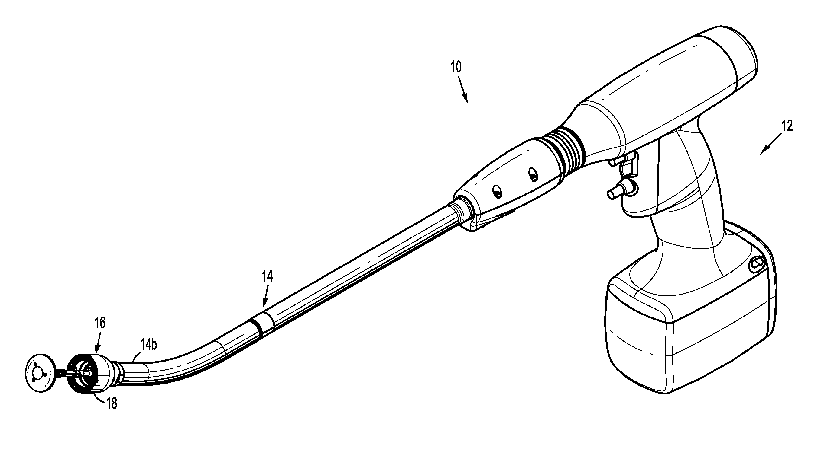
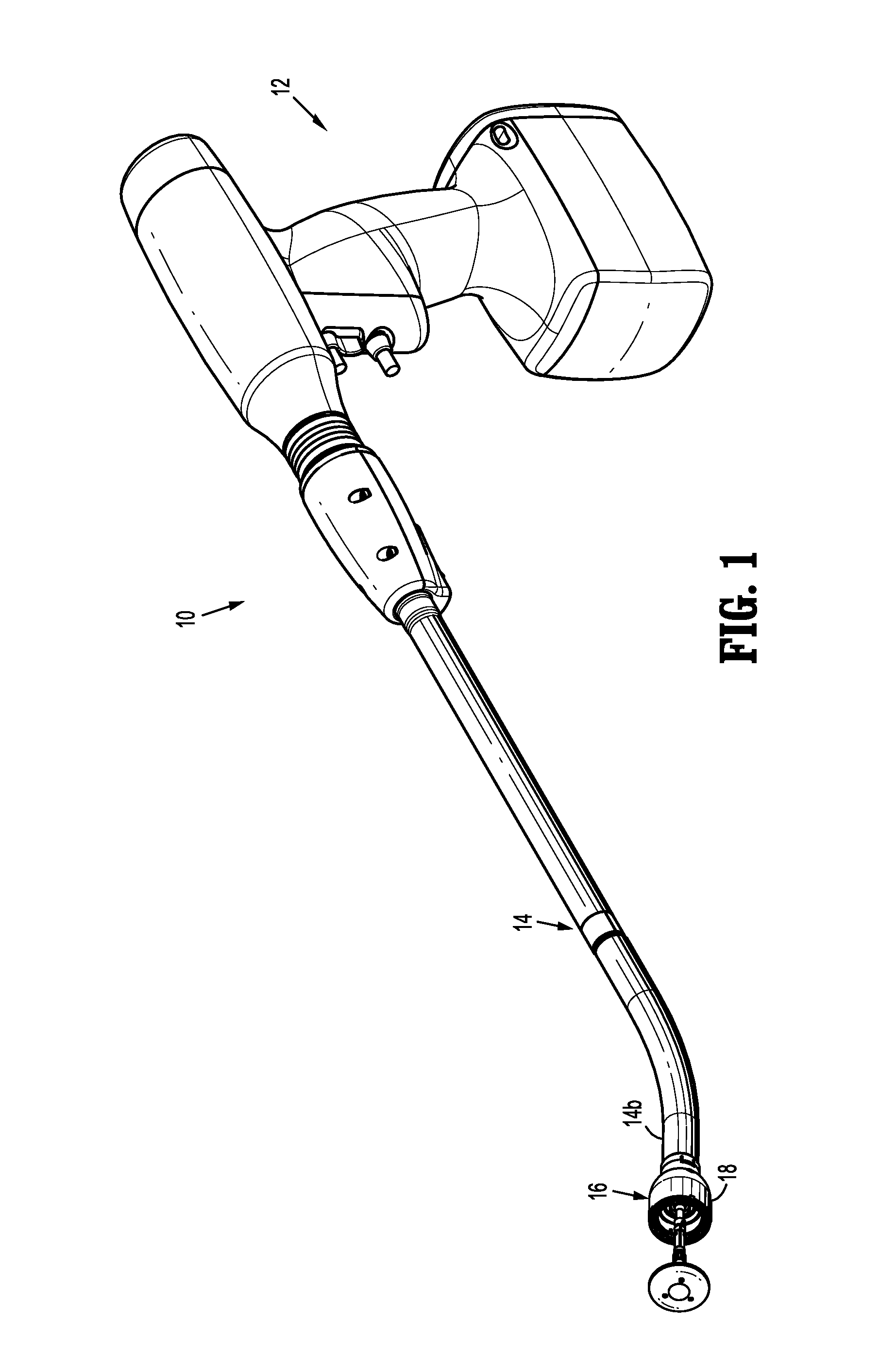
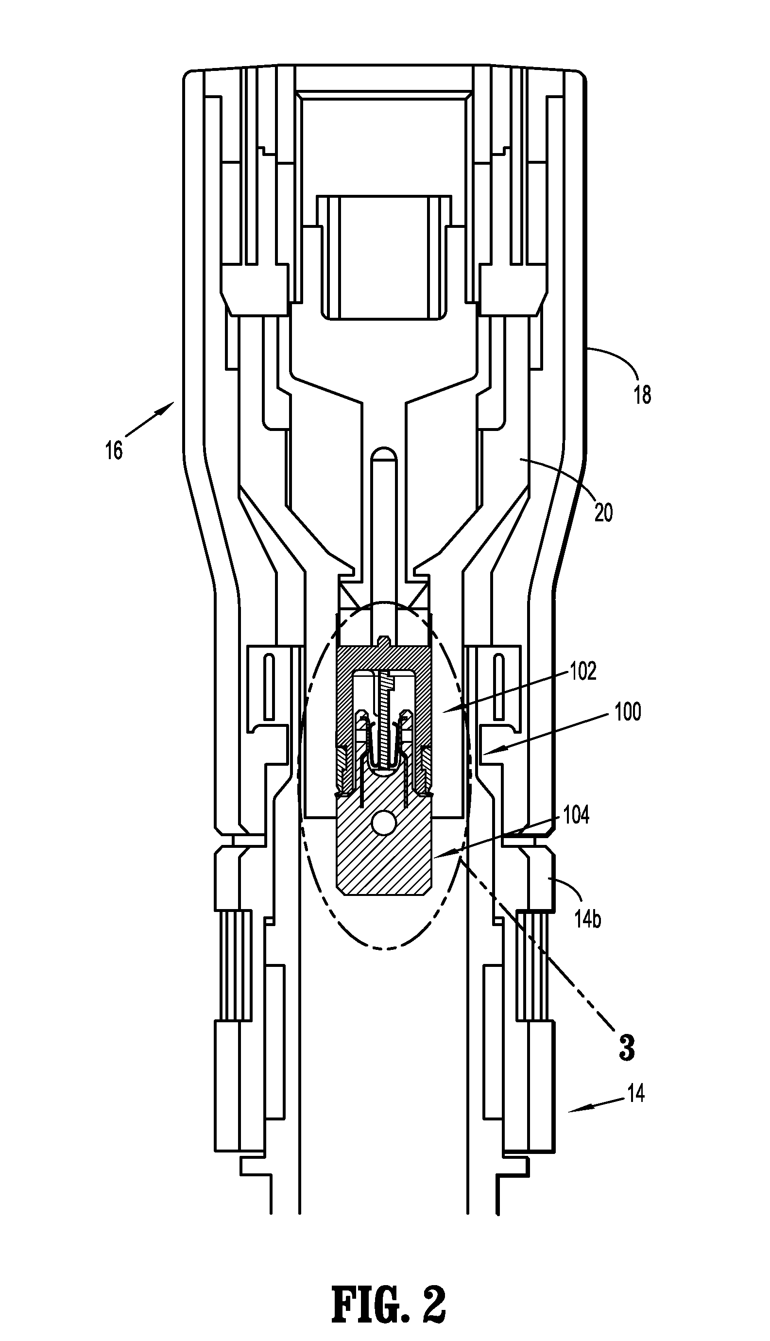
[0032]With reference initially to FIG. 1, a surgical stapling instrument including a chip assembly according to the present disclosure is shown generally as circular stapler 10. Circular stapler 10 includes a handle assembly 12, an adapter assembly 14 removably attached to, and extending distally from handle assembly 12, and a reload assembly 16 selectively secured to a distal end 14b of adapter portion 14. A detailed description of handle assembly 12 and adapter assembly 14 is provided in commonly owned U.S. Patent Appl. Publ. No. 2012 / 00...


PUM

PropertyMeasurementUnit
thicknessaaaaaaaaaa
densityaaaaaaaaaa
sizesaaaaaaaaaa

Abstract

A surgical instrument system is disclosed, the system including a first component and a second component, the first component being a reload assembly and the second component being selected from a group consisting of a handle assembly and an adapter assembly, the surgical instrument system including at least one chip assembly having a housing assembly on the first component, the housing assembly containing a chip, and a plug assembly on the second component, the chip having data for, and being configured to, prevent use of the reload assembly if the reload assembly is unauthorized.

Description

BACKGROUND[0001]1. Technical Field[0002]The present disclosure relates to surgical instruments having a reusable handle and a disposable end effector. More particularly, the present disclosure relates to a chip assembly for use in a stapling instrument having a disposable loading unit.[0003]2. Background of Related Art[0004]Powered surgical instruments for use in endoscopic procedures are known. Typically, such instruments include a reusable handle assembly and a disposable end effector. An adapter assembly connects the end effector to the handle assembly. In the case of a surgical stapler, the end effector includes a disposable cartridge or reload assembly that is changed after each firing of the surgical stapler. To reduce costs and shorten procedure times, the handle assemblies are generally configured for use with a variety of reload assemblies of various configurations for use on tissue having different properties, i.e., thickness, density. For example, the different reload ass...

Claims


Application Information

Patent Timeline
Patent Type & Authority Applications(United States)
IPC IPC(8): A61B17/068
CPCA61B17/068H01R12/57H01R12/721A61B17/1155H01R13/5224A61B17/115A61B2017/0023A61B2017/0046A61B2017/00017A61B2017/00398A61B2017/00473A61B2017/00477A61B90/90A61B90/98A61B2090/0803A61B2090/0814H05K5/069H05K7/1427A61B2017/00734
Inventor PENNA, CHRISTOPHERSAPIENZA, JONATHAN W.NELSON, ANNERICHARD, PAUL D.
Owner TYCO HEALTHCARE GRP LP
Why Eureka
Try Eureka