

Tire
a technology of tires and wheels, applied in the field of tires, can solve the problems of limited recycling applications of used rubber
- Summary
- Abstract
- Description
- Claims
- Application Information
AI Technical Summary
Benefits of technology
Problems solved by technology
Method used
Image

Examples
first exemplary embodiment
[0049]Explanation next follows regarding a tire of a first exemplary embodiment of the present invention, with reference to FIG. 1 to FIG. 4.
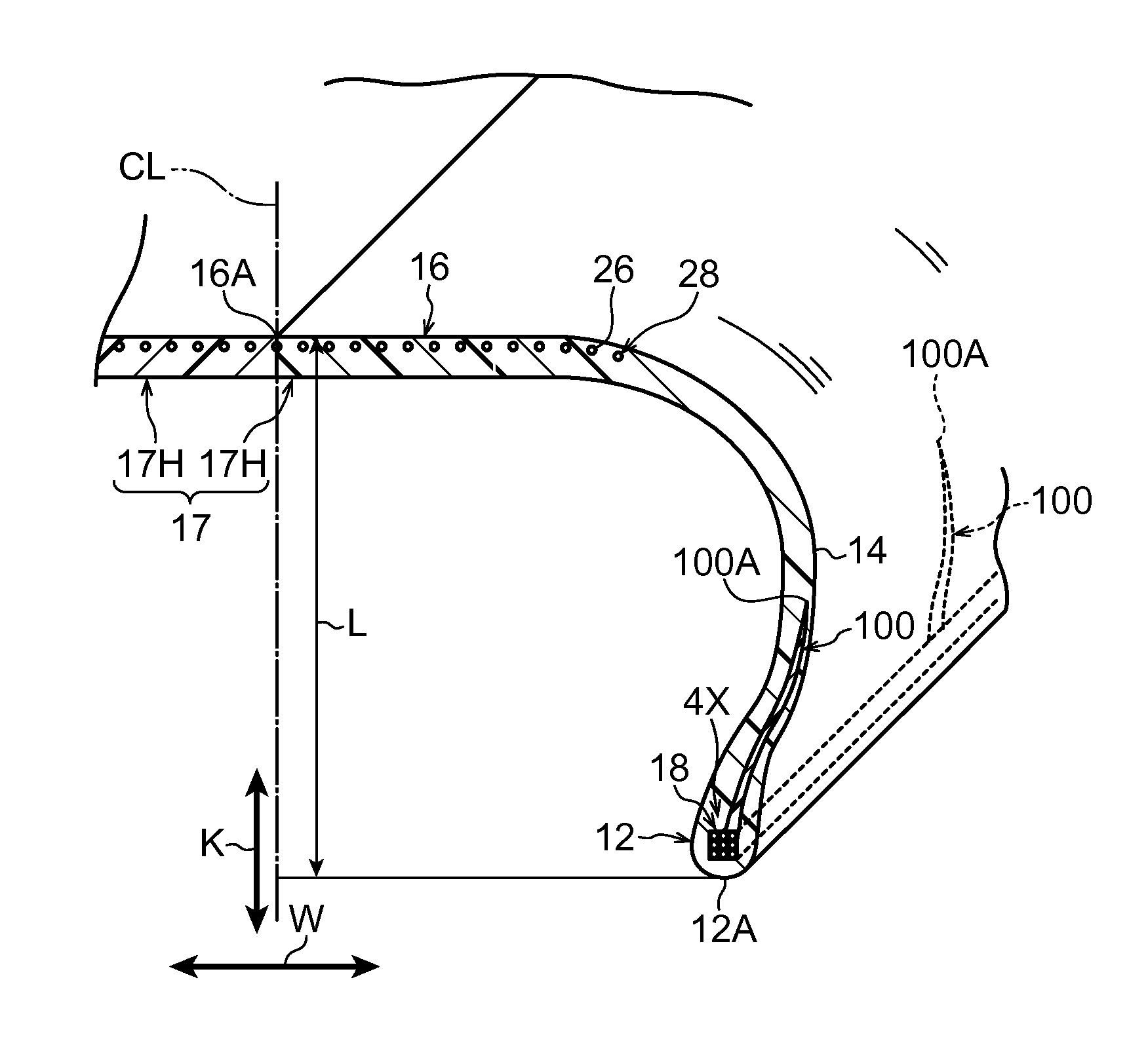
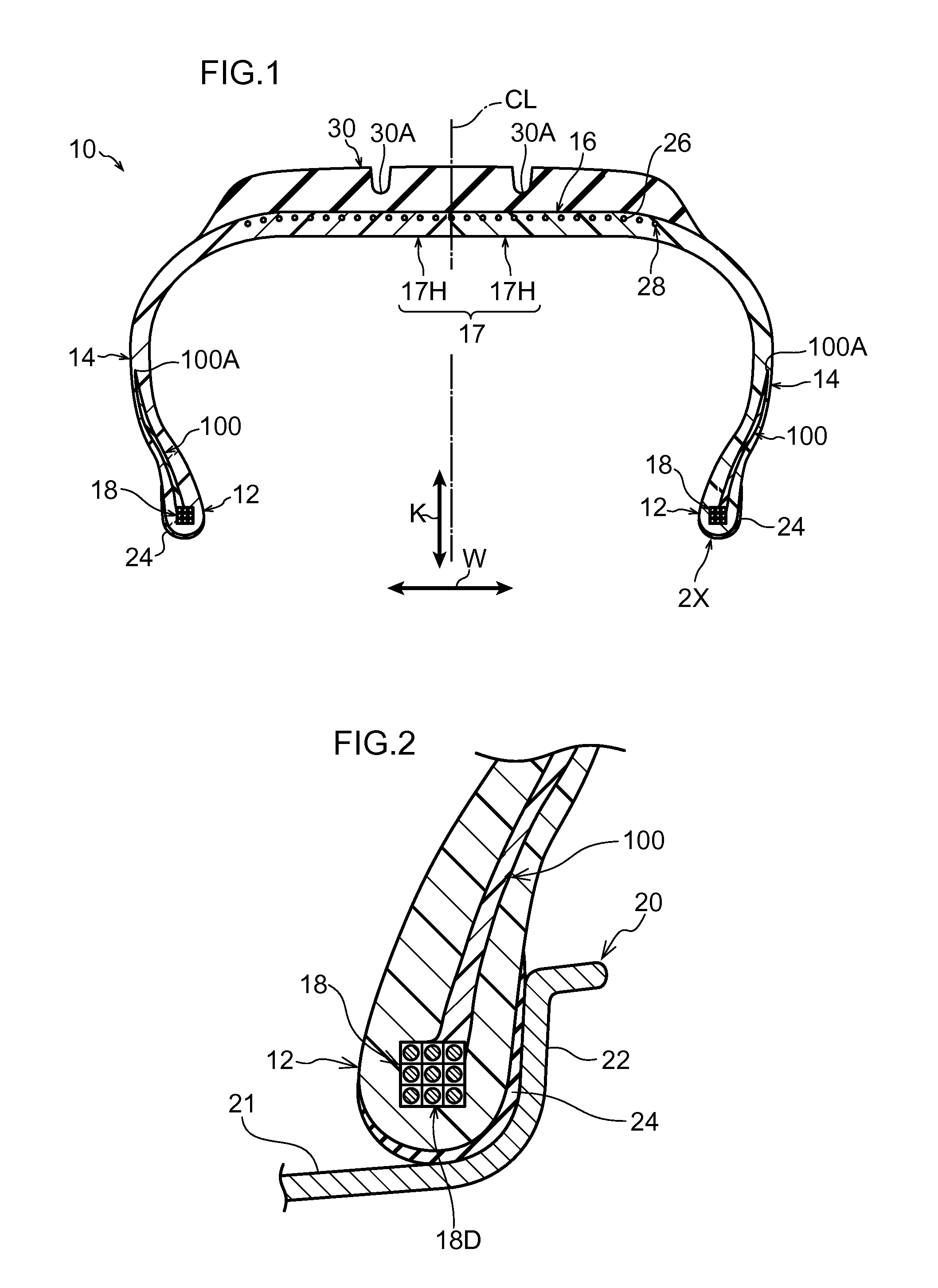
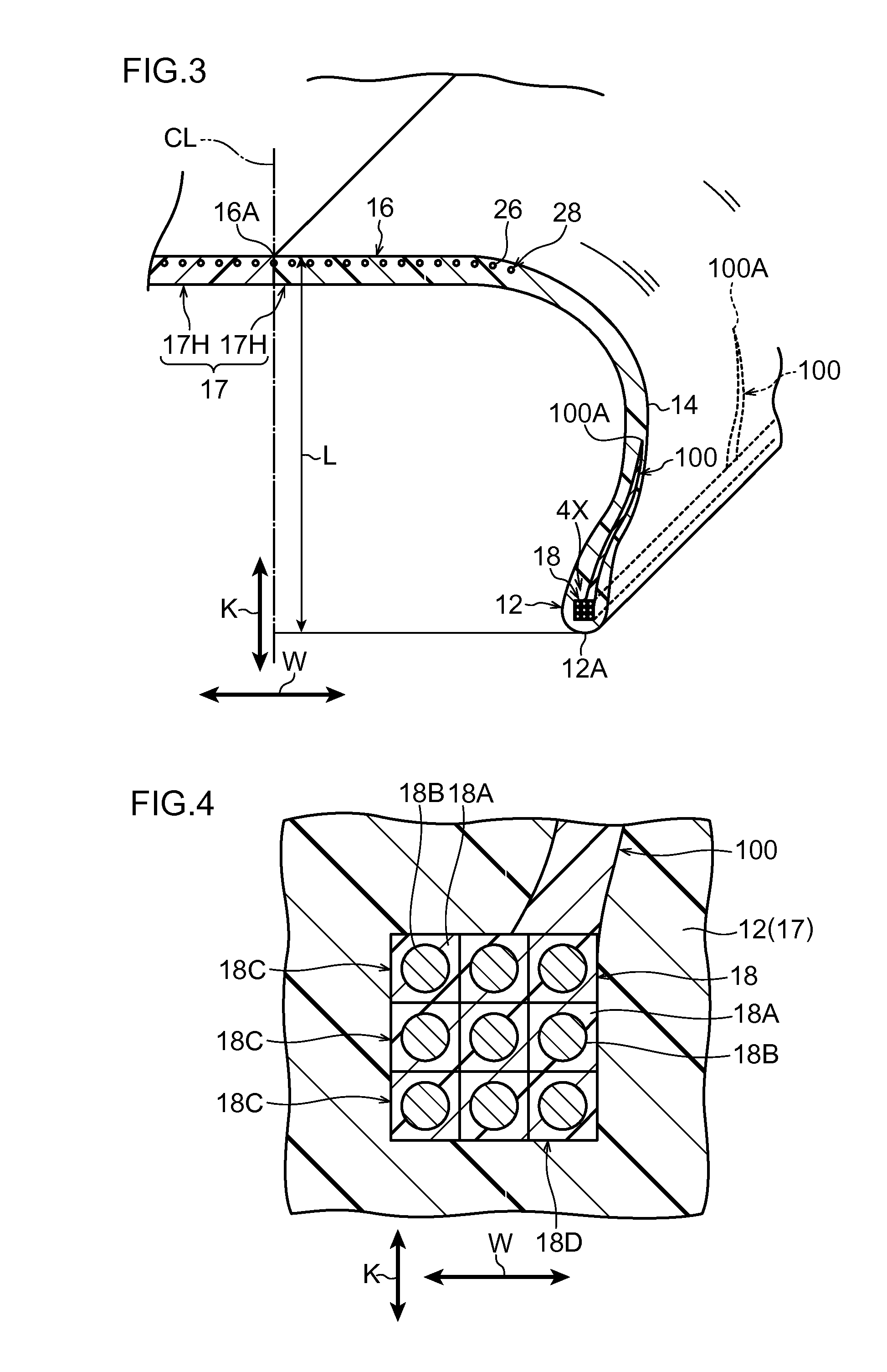
[0050]As illustrated in FIG. 1, a tire 10 of the first exemplary embodiment exhibits a cross-section profile that is substantially the same as a conventional ordinary rubber pneumatic tire. Note that the tire width direction is indicated in FIG. 1 to FIG. 4 by arrow W, and the tire radial direction is indicted by arrow K.
[0051]The tire 10 includes a tire case 17, serving as an example of a tire frame member that forms a tire frame section. The tire case 17 is configured by forming a resin material 17A for tire frame use (referred to below as “frame resin material”) in a circular ring shape.
[0052]The tire case 17 is configured including a pair of bead sections 12 disposed at a separation from each other in the tire width direction, a pair of side sections 14 that respectively extend from the pair of bead sections 12 toward the tire radial direct...
second exemplary embodiment
[0167]Explanation next follows regarding a tire of a second exemplary embodiment according to the present invention, with reference to FIG. 16. Note that the same reference numerals are appended to similar configuration to that of the first exemplary embodiment, and further explanation omitted thereof.
[0168]As illustrated in FIG. 16, a tire 110 of the present exemplary embodiment is configured the same as the tire 10 of the first exemplary embodiment, except for in the configuration of extension portions 112. Explanation accordingly follows regarding the configuration of the extension portions 112. Note that the seal layer 24 and the tread 30 are omitted from illustration in FIG. 16.
[0169]The extension portions 112 of the present exemplary embodiment are inserted into the crown section 16. More specifically, leading end portions 112A of the extension portions 112 extend as far as the vicinity of the tire equatorial plane CL. Note that the resin material for forming the extension por...
third exemplary embodiment
[0172]Explanation next follows regarding a tire of a third exemplary embodiment according to the present invention, with reference to FIG. 17. Note that the same reference numerals are appended to similar configuration to that of the first exemplary embodiment, and further explanation omitted thereof.
[0173]As illustrated in FIG. 17, a tire 120 of the present exemplary embodiment is configured the same as the tire 10 of the first exemplary embodiment, except for in the configuration of extension portions 122. Explanation accordingly follows regarding the configuration of the extension portions 122. Note that the seal layer 24 and the tread 30 are omitted from illustration in FIG. 17.
[0174]Each of the extension portions 122 of the present exemplary embodiment is inserted into the respective side section 14, and is continuous in the tire circumferential direction. The leading end portions 122A of the extension portions 122 extend as far as a tire radial direction intermediate portion o...
PUM
| Property | Measurement | Unit |
|---|---|---|
| Adhesivity | aaaaa | aaaaa |
| Plasticity | aaaaa | aaaaa |
Abstract
Description
Claims
Application Information