Optical scanning apparatus and image forming apparatus

Active Publication Date: 2015-03-26
CANON KK
View PDF3 Cites 3 Cited by
  • Summary
  • Abstract
  • Description
  • Claims
  • Application Information

AI Technical Summary

Benefits of technology

This patent describes an optical scanning apparatus used in image forming devices. The apparatus includes a light source, a deflection unit, an optical box, a cover, a transparent member, and a shutter member. The shutter member can cover the transparent member to clean it. The technical effect of the invention is to provide an improved way of scanning and cleaning the photosensitive member in image forming devices.

Problems solved by technology

As a result, the photosensitive drum surface is not appropriately irradiated with the light beam, thereby leading to such a problem that an image defect occurs.
This may hamper downsizing of the apparatus, in the configuration of the optical scanning apparatus discussed in Japanese Patent Application Laid-Open No. 2009-151111.
This may cause the cleaned dust to fall in a corner portion “D” formed by the emission window 212 and the shutter 216, which may lead to occurrence of an image defect.

Method used


Image

  • Optical scanning apparatus and image forming apparatus
  • Optical scanning apparatus and image forming apparatus
  • Optical scanning apparatus and image forming apparatus

Examples


Embodiment Construction

[0018]Various exemplary embodiments, features, and aspects of the invention will be described in detail below with reference to the drawings.

[Image Forming Apparatus]

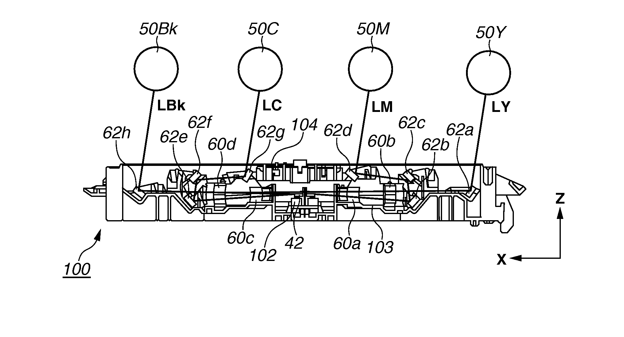
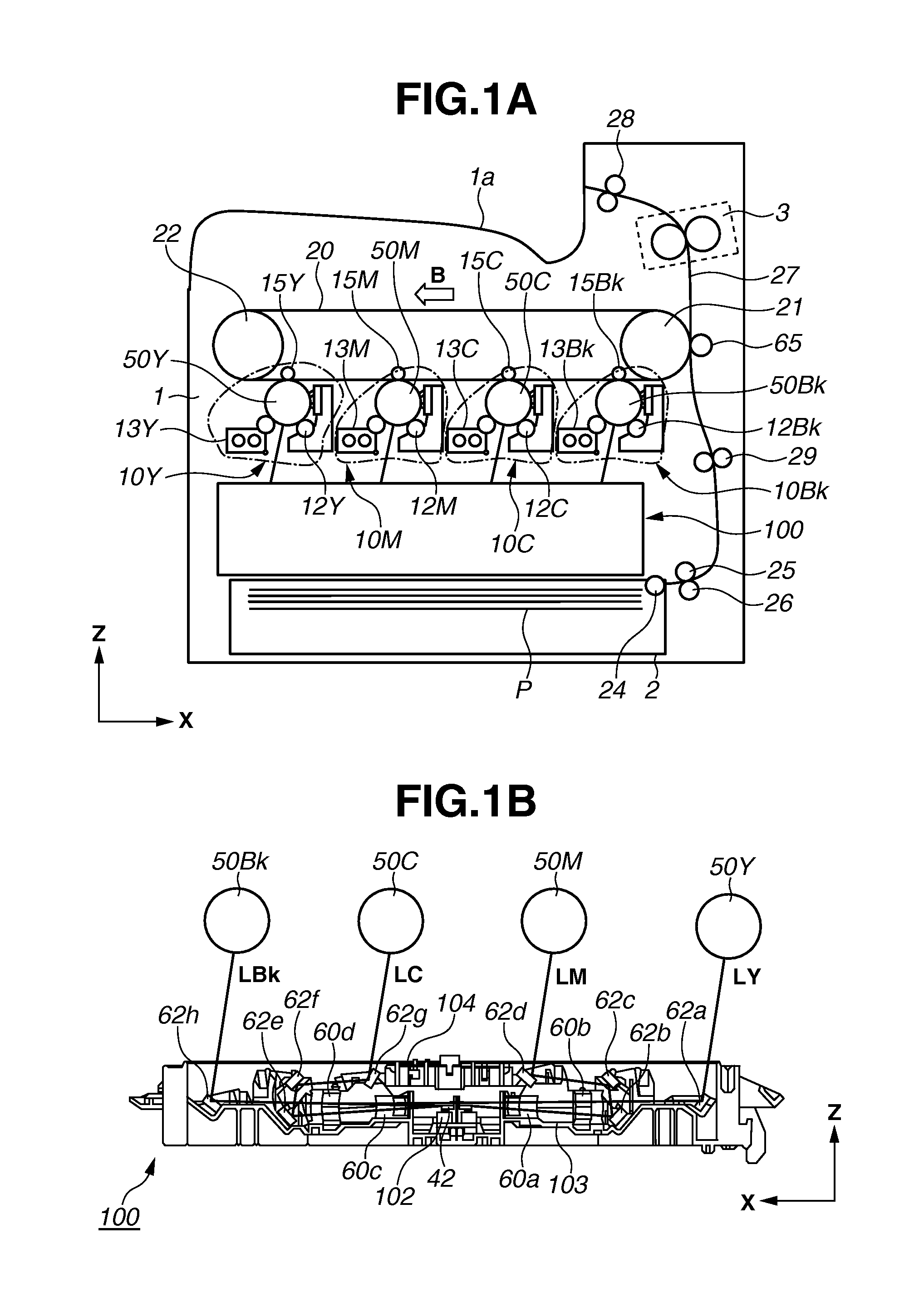
[0019]A configuration of an image forming apparatus according to an exemplary embodiment will be described. FIG. 1A is a schematic configuration diagram illustrating an overall configuration of a tandem type color laser beam printer according to the present exemplary embodiment. This laser beam printer (hereinafter referred to as “printer”) includes four image forming engines 10Y, 10M, 10C, and 10Bk (indicated by a dashed line) each of which forms a toner image of yellow (Y), magenta (M), cyan (C), and black (Bk), respectively. The printer further includes an intermediate transfer belt 20 onto which the toner image is transferred from each of the image forming engines 10Y, 10M, 10C, and 10Bk. A toner image resulting from multiple transfer on the intermediate transfer belt 20 is transferred to a recording sheet P that is...


PUM


Abstract

An optical scanning apparatus and an image forming apparatus including the optical scanning apparatus, the optical scanning apparatus includes a dust-proof shutter having an opening portion. The opening portion has a side-surface opening portion and a top-surface opening portion. The side-surface opening portion is formed in a side surface of the dust-proof shutter. A cleaning member used for cleaning a dust-proof glass is inserted through the side-surface opening portion. The top-surface opening portion guides a moving direction of the cleaning member inserted through the side-surface opening portion, to a direction along a longitudinal direction of the dust-proof glass. When the dust-proof shutter is located at a first position, a light beam passed through the dust-proof glass passes through the top-surface opening portion.

Description

BACKGROUND[0001]1. Field of the Disclosure[0002]The present disclosure relates to an optical scanning apparatus and an image forming apparatus. The present invention particularly relates to an optical scanning apparatus including a shutter member provided to open and close an emission portion through which a light beam passes, and an image forming apparatus including the optical scanning apparatus.[0003]2. Description of the Related Art[0004]In an image forming apparatus using an electrophotographic technology, such as a copying machine and a laser beam printer, a light beam emitted from an optical scanning apparatus passes through components, such as a rotating polygon mirror (a polygon mirror), a scanning lens, and a reflection mirror. The light beam is then condensed in a spot shape, on a photosensitive drum surface that is charged electrically. At this moment, an electric potential on the photosensitive drum surface changes according to intensity of the light beam, and then tone...

Claims


Application Information

Patent Timeline
IPC IPC(8): B41J2/385G02B26/08
CPCG03G15/04G02B26/125G02B27/0006G03G15/04045G03G21/1666
Inventor MOMOKA, TOSHIKI
Owner CANON KK
Why Eureka
Try Eureka