Beam support

a beam support and beam technology, applied in the direction of fixed installation, semiconductor devices for light sources, lighting and heating apparatus, etc., can solve the problems of not being able to support led lights, rolled sheet metal beams used in the grid of conventional prior art suspended ceilings, etc., and achieve the effect of easy manual insertion into the connector

Inactive Publication Date: 2015-03-26
WORTHINGTON ARMSTRONG VENTURE
View PDF6 Cites 146 Cited by
  • Summary
  • Abstract
  • Description
  • Claims
  • Application Information

AI Technical Summary

Benefits of technology

[0014]The second cross beam connector, without any attached cross beam, is manually inserted into the slot, to connect with the opposing first cross beam connector on the end of the first cross beam, already in the slot, and the main beam. The second cross beam connector is desirably modified to provide an extended portion that enables the connector to be more easily manually inserted into the connector.

Problems solved by technology

The rolled sheet metal beams that are used in the grid of conventional prior art suspended ceilings, are not suitable to support LED lights.

Method used


Image

  • Beam support
  • Beam support
  • Beam support

Examples


Embodiment Construction

[0024]The '238 patent is representative of the prior art connection on which this invention is based. The connection itself, and the method of making such connection, is set forth in detail in the '238 patent.

[0025]Such connection conforms to building codes, including their requirements as to earthquake resistance.

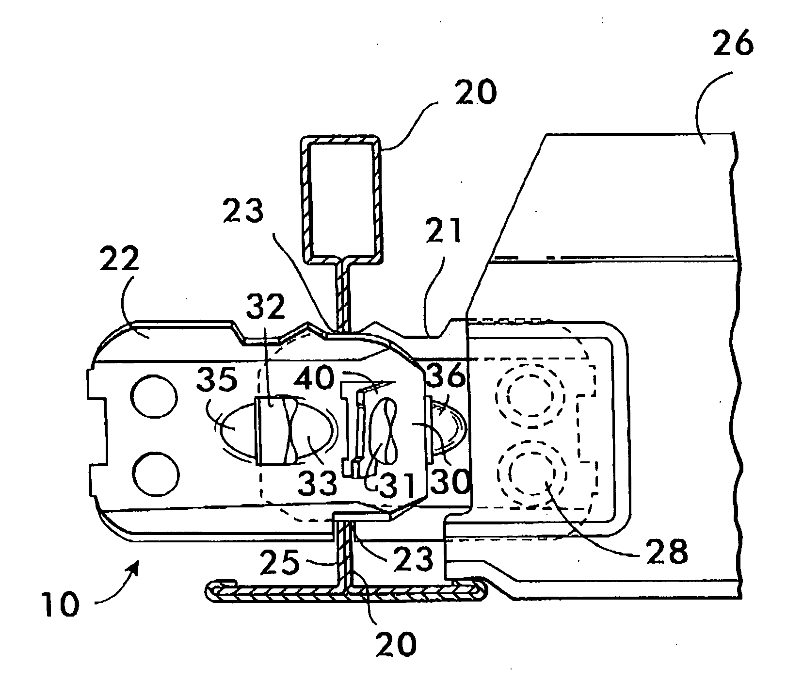
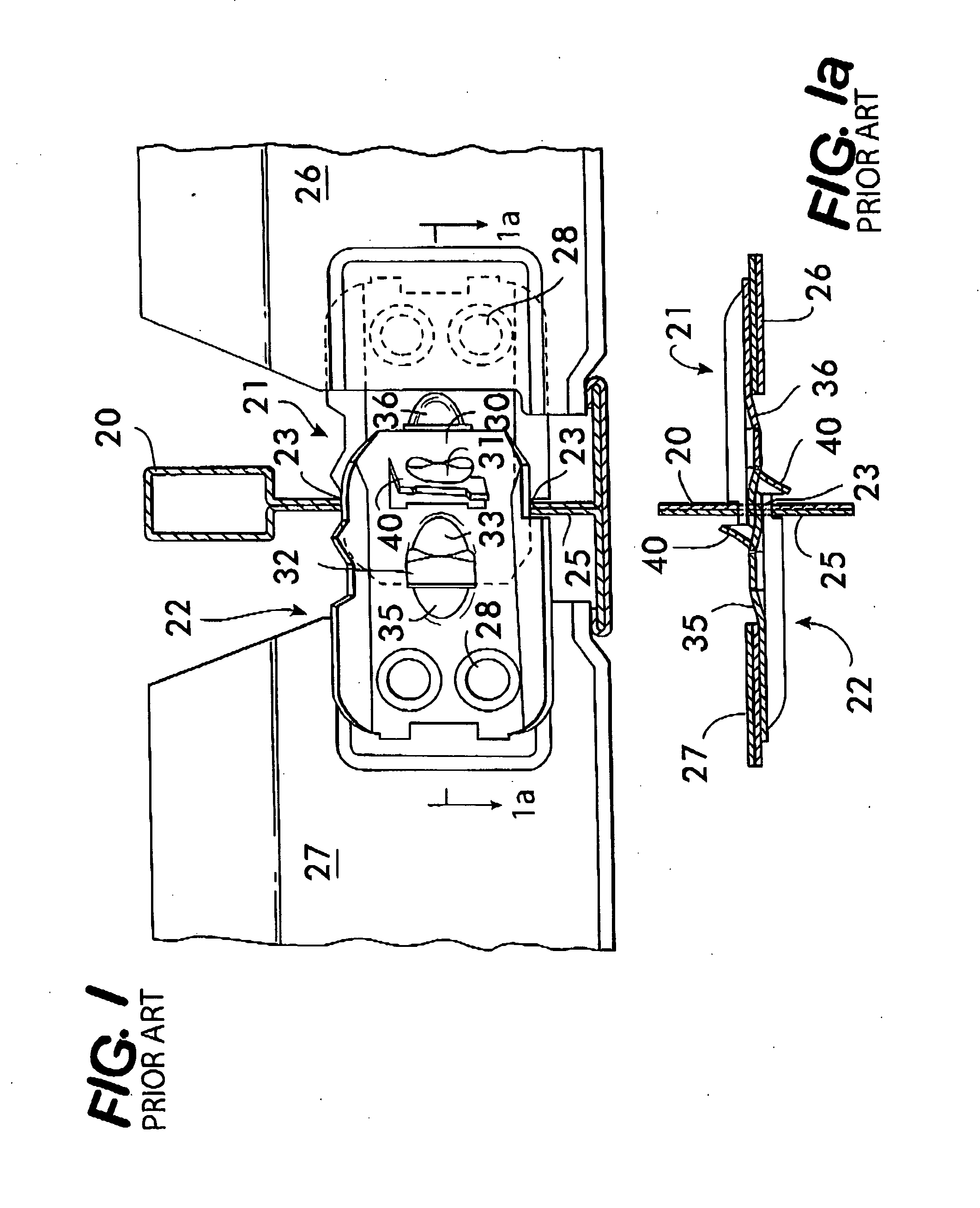
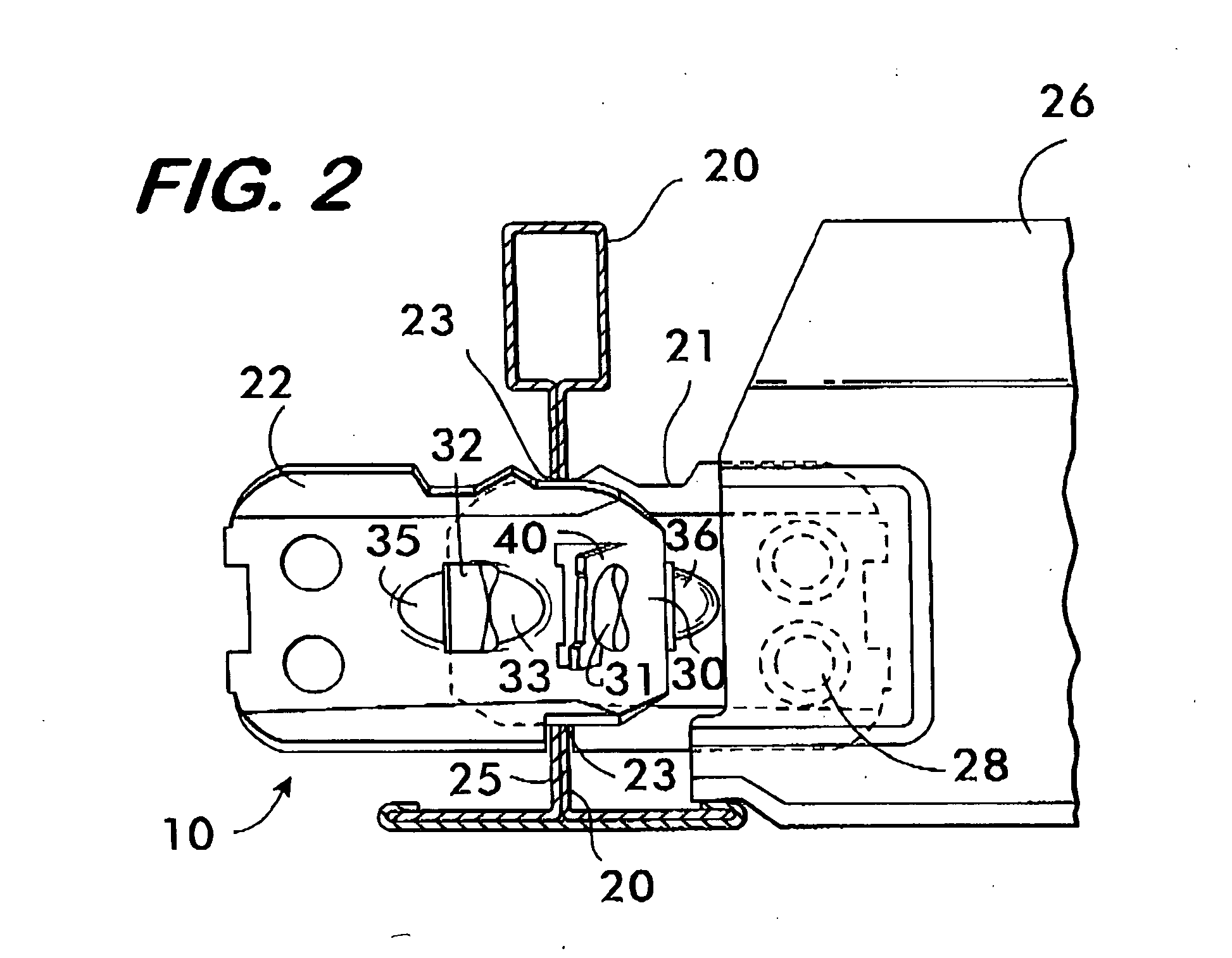
[0026]The prior art '238 connection on which the present invention is based, is shown in FIGS. 1 and 1a. Main beam 20, shown in cross section, extends longitudinally in a ceiling grid that supports panels. Identical first cross beam connector 21 and second cross beam connector 22, are attached to first cross beam 26 and second cross beam 27 respectively, by rivets 28. To make the prior art connection of FIG. 1, the first and second cross beam connectors 21 and 22, by means of attached first 26 and second 27 cross beams, are stabbed through a slot 23 in the web 25 of the main beam 20 and interconnect with each other and with the main beam 20.

[0027]In such prior art connecti...


PUM

PropertyMeasurementUnit
timeaaaaaaaaaa
resistanceaaaaaaaaaa
earthquake resistanceaaaaaaaaaa

Abstract

Selected connections in a prior art suspended panel ceiling are modified to provide fixed cantilevered extensions that support aluminum beams (ABs) with light emitting diode (LED) lights. The ABs with LED lights can be installed in the suspended ceiling to the fixed cantilevered extensions after the prior art portion of the suspended ceiling is completed.
To create a fixed cantilevered extension, a second cross beam connector, preferably modified to provide an extended portion, is alone stabbed into a connection, without any attached second cross beam. Such fixed cantilevered extension is capable of subsequently having attached thereto, for support, a rolled aluminum beam (AB) with LED lights, after the prior art suspended ceiling is installed.
The installation of the ABs with LED lights, subsequent to the construction of the suspended ceiling with the supports of the invention, does not affect the ceiling resistance to earthquakes.

Description

BACKGROUND OF THE INVENTION[0001]1. Field of the Invention[0002]Suspended ceilings are used extensively in commercial and industrial buildings. In such ceilings, a metal grid framework, formed of interconnected T-beams, is hung from a structural ceiling by wires. The beams are roll-formed from continuous strips of sheet metal.[0003]The grid supports panels in rectangular openings formed in the grid.[0004]Such ceilings must resist earthquake tremors in accordance with applicable building codes:[0005]This invention relates to a support, at selected locations in such grid, for an aluminum beam (AB) with light emitting diode (LED) lights. The support is installed at the time the suspended ceiling is constructed. The AB's with lights are installed later. By means of the invention, the suspended ceiling sustains its resistance to earthquakes with the AB's with LED lights installed, as in a prior-art ceiling without such AB's.[0006]2. Prior Art[0007]Suspended ceilings having folded sheet m...

Claims


Application Information

Patent Timeline
Patent Type & Authority Applications(United States)
IPC IPC(8): F21S8/04F21K99/00
CPCF21K9/30F21S8/046E04B9/068E04B9/12E04B9/10E04B9/122Y10T29/49117
Inventor SAREYKA, BRETT W.
Owner WORTHINGTON ARMSTRONG VENTURE
Why Eureka
Try Eureka