
Bone position tracking system

a tracking system and bone technology, applied in the field of bone position tracking system, can solve the problems of inability to correlate the change in length of the strut, the inability to plan and the inability to accurately predict the movement of the bone fragment relative to the fixed bone fragmen

Active Publication Date: 2015-03-26
STRYKER EURO OPERATIONS HLDG LLC
View PDF3 Cites 10 Cited by
  • Summary
  • Abstract
  • Description
  • Claims
  • Application Information

AI Technical Summary

Benefits of technology

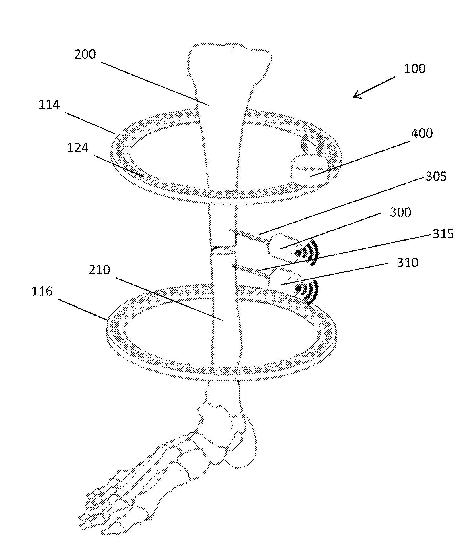
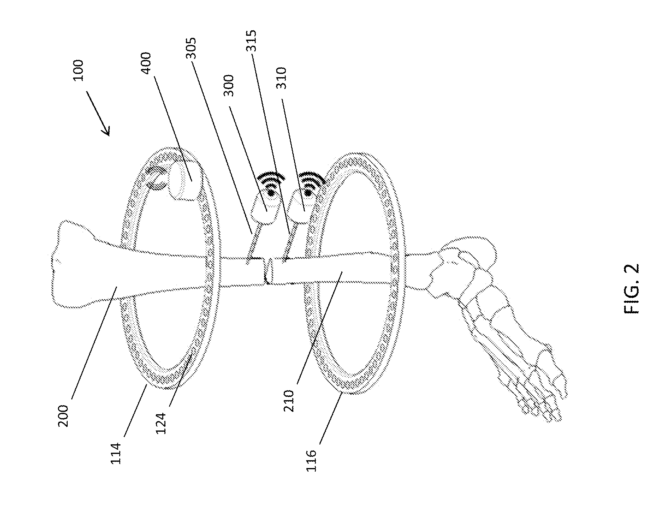
The present invention is about a system and method for tracking the position of bone fragments during a deformity correction. The system includes first and second support members connected to the bone fragments, and first and second tracking devices that transmit tracker location data to a receiver. The receiver determines the real position of the bone fragments based on the tracker location data and compares it to the deformity correction plan. The system can adjust the position of the support members based on the comparison and reprogram the deformity correction plan accordingly. The technical effects of this invention include improved accuracy in bone positioning and correction of errors in real bone position compared to the deformity correction plan.

Problems solved by technology

Such errors between planned movements of the bone fragment relative to the fixed bone fragment may occur, for example, because of incorrect adjustments to the external fixation device or bending and other deformation of wires, pins, or other devices connecting the bone fragments to the external fixation device.
Errors may also result from imprecision in, or deformation of, other components of the external fixation device, or from human error in following the deformity correction plan.
However, not only is it difficult to correlate the change in length of a strut and the position and orientation of respective bone fragments, this relationship is not always accurate based on the aforementioned deformation of wires, pins, or other devices connecting the bone fragments to the external fixation device.

Method used


Image

  • Bone position tracking system
  • Bone position tracking system
  • Bone position tracking system

Examples


Embodiment Construction

[0014]As used herein, the term “distal” means more distant from the heart and the term “proximal” means closer to the heart. The term “inferior” means toward the feet and the term “superior” means towards the head. The term “anterior” means towards the front part of the body or the face and the term “posterior” means towards the back of the body. The term “medial” means toward the midline of the body and the term “lateral” means away from the midline of the body.

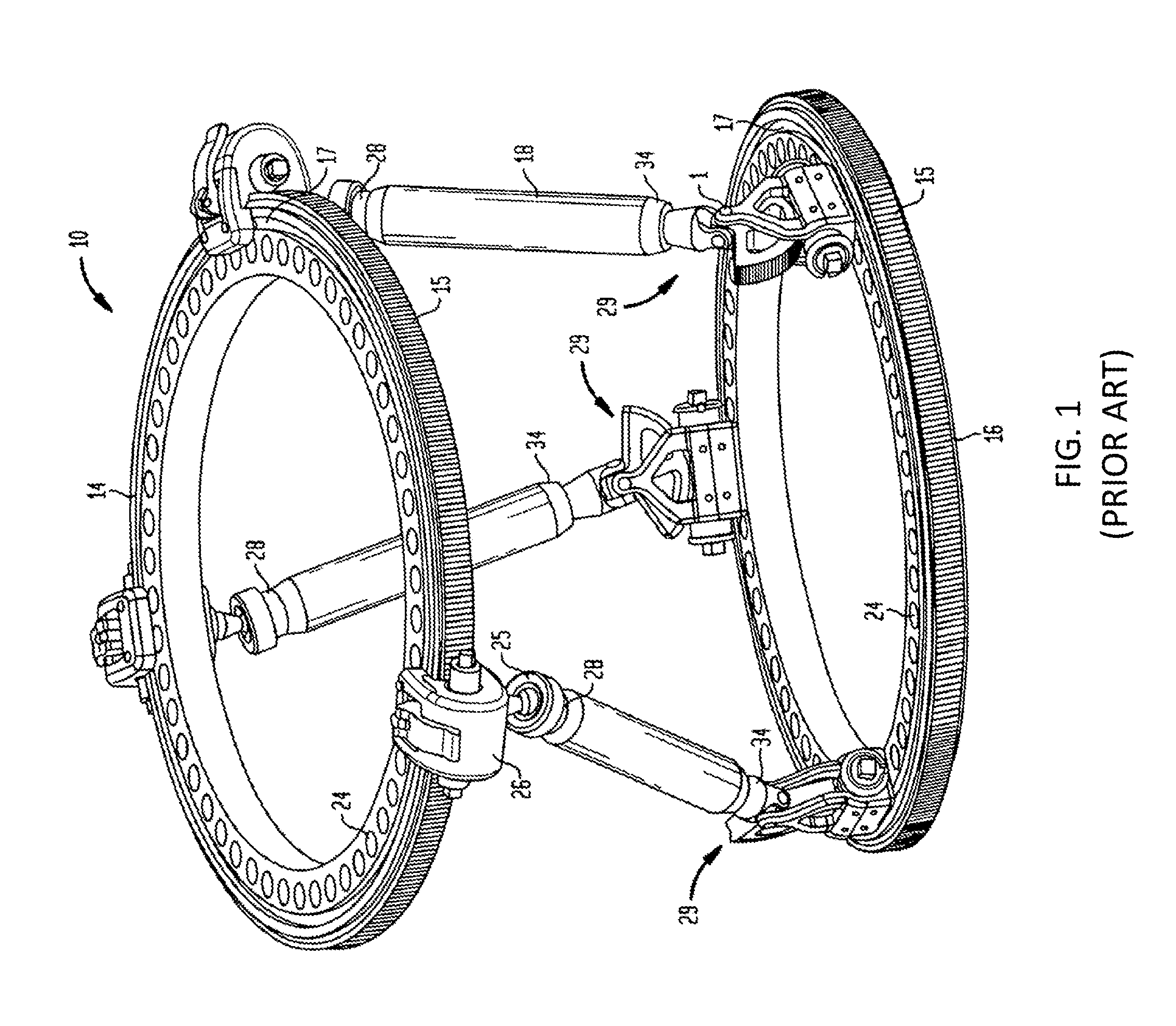
[0015]Referring to FIG. 1, there is shown the external fixation system 10 for correcting a bone deformity according to the prior art. The external fixation system 10 may be utilized with any long bone, in particular, the tibia and the femur.

[0016]As shown in FIG. 1, the external fixation system 10 includes a first ring 14 and a second ring 16. In some embodiments, both rings 14, 16 are identical. Each ring 14 includes a worm gear 15 formed around its outer circumference. Two grooves 17 are formed in the upper and lower surfa...


PUM


Abstract

A method of correcting a bone deformity includes fixing first and second support members to first and second fragments of a bone, respectively. The first support member may have a receiver connected thereto. First and second tracking devices are connected to the first and second bone fragments, respectively. A deformity correction plan is determined, and a position of the first support member is adjusted relative to the second support member based on the plan. Location data is transmitted from the first and second trackers to the receiver. Based on the tracker location data, a real position of the first and second bone fragments is determined. The real position of the first and second bone fragment is compared to the deformity correction plan, and the deformity correction plan is reprogrammed based on the comparison. The first and second support members may then be adjusted based on the reprogrammed deformity correction plan.

Description

FIELD OF THE INVENTION[0001]The present invention relates to systems and methods for tracking the position and orientation of a plurality of bone fragments with respect to one another, and in particular it relates to a tracking system for use with an external fixation device attached to a plurality of bone segments.BACKGROUND OF THE INVENTION[0002]External fixation frames may be used to correct skeletal deformities. The Ilizarov external fixation devices, for example, are widely used for this purpose. The Ilizarov-type devices may be used to translate bone segments by manipulating rings connected to each bone segment and a plurality of threaded rods connected to the manipulation rings.[0003]A bone fragment can be moved, in general, from its original position as in a nonunion or malunion or from its intended position as in congenital deformities along six separate axes, a combination of three orthogonal translational axes (e.g., typical “X,”“Y” and “Z” axes) and three orthogonal rota...

Claims


Application Information

Patent Timeline
Patent Type & Authority Applications(United States)
IPC IPC(8): A61B17/62
CPCA61B17/62A61B17/66A61B2034/2051
Inventor SINGH, MANOJ KUMAR
Owner STRYKER EURO OPERATIONS HLDG LLC
Learn More