Prosthetic socket with integrated cooling channels

a technology of prosthetic sockets and cooling channels, applied in the field of prosthetic sockets with integrated cooling channels, can solve the problems of reducing the quality of life of amputee patients, affecting the rehabilitation of amputee patients, and complex prosthetic environmen

Inactive Publication Date: 2015-04-16
THE UNIVERSITY OF AKRON
View PDF4 Cites 11 Cited by
  • Summary
  • Abstract
  • Description
  • Claims
  • Application Information

AI Technical Summary

Benefits of technology

The present invention provides a residual limb prosthesis that includes a socket for receiving a residual limb, a coil-shaped channel extending from the inlet to the outlet, and an air mover for circulating air through the coil-shaped channel. The residual limb prosthesis can be made using additive manufacturing materials, such as plastic or metal alloys, and can be designed for individuals with different anatomy. The invention also includes a wearable structure with a socket for being worn over an individual's anatomy and an air mover for air circulation. The technical effect of the invention is to provide a comfortable and effective prosthesis for individuals with residual limbs that can improve their quality of life.

Problems solved by technology

Therefore, an unnatural environment is created around the residual limb by this trapped heat, often causing the residual limb to sweat excessively leading to numerous dermatologic conditions, such as allergic contact dermatitis, microorganism infections, and verrucous hyperplasia.
Atypical loading conditions experienced by a residual limb can exacerbate these skin problems, often reducing the quality of life for the amputee patient.
Furthermore, amputee patient rehabilitation is hindered by the physical and psychological burdens caused by these conditions.
The prosthetic environment is complex, making it difficult to model without making numerous assumptions and simplifications.
Some researchers have assumed heat generation by the residual limb to be uniform across the limb surface, however, this does not represent typical in vivo conditions.
Furthermore, it is difficult to quantify a “cooling” effect and what it means to each individual amputee patient.

Method used


Image

  • Prosthetic socket with integrated cooling channels
  • Prosthetic socket with integrated cooling channels
  • Prosthetic socket with integrated cooling channels

Examples


Embodiment Construction

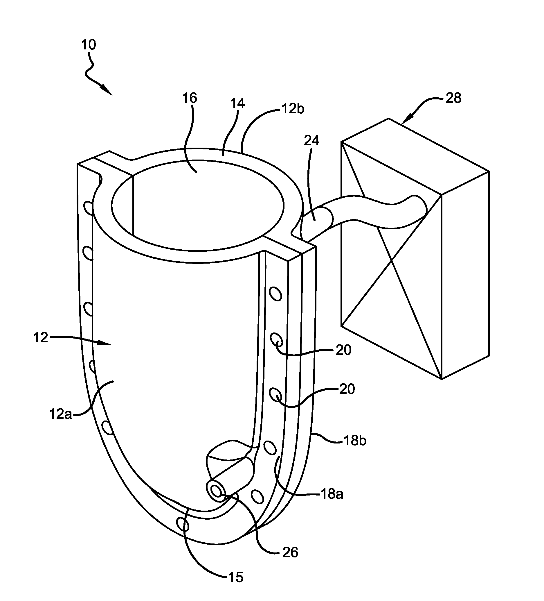
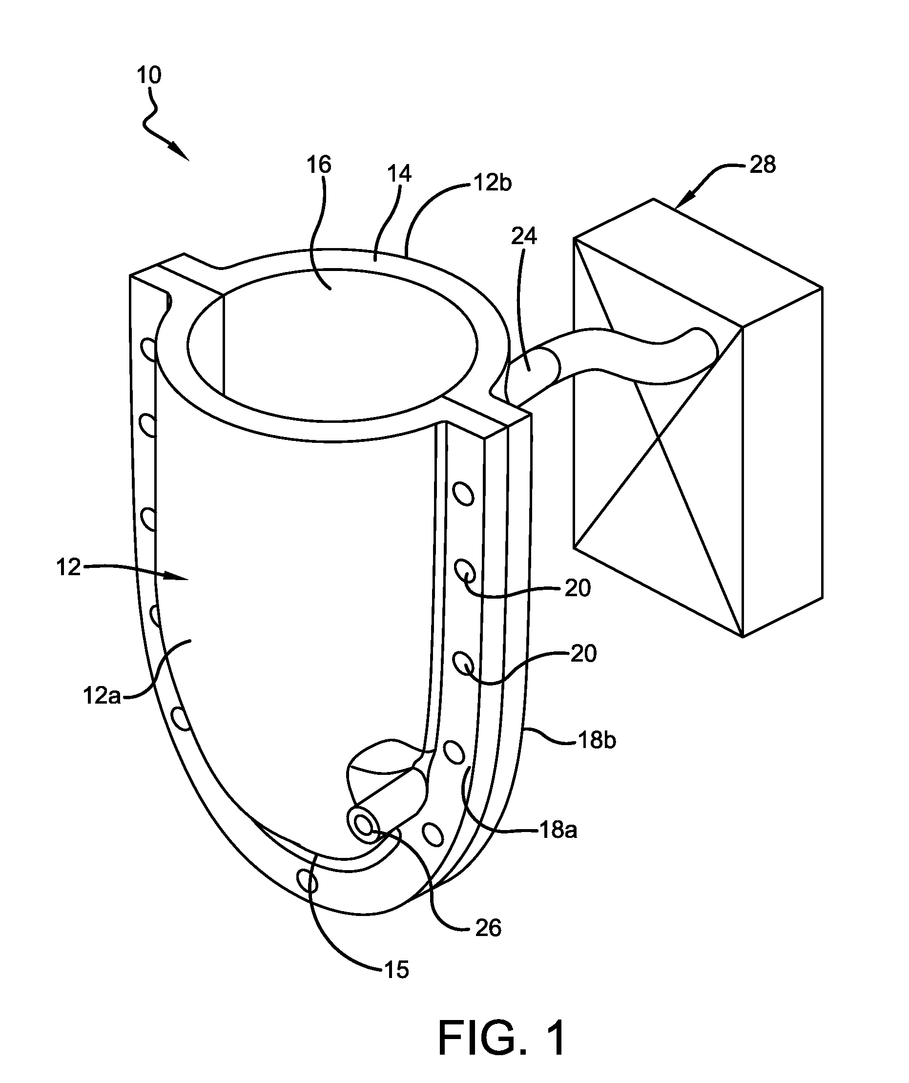
[0022]With reference to FIGS. 1-2, a residual limb prosthesis in accordance with this invention is shown and designated by the numeral 10. The residual limb prosthesis 10 includes a socket 12 for receiving a residual limb, wherein the socket 12 includes a socket wall 14 defining a limb-receiving surface 16. In some embodiments, the limb-receiving surface 16 is the inner surface of the socket wall 14, in order to come in direct contact with the limb in the socket 12. A liner, not shown but generally known in the art, might also be employed.

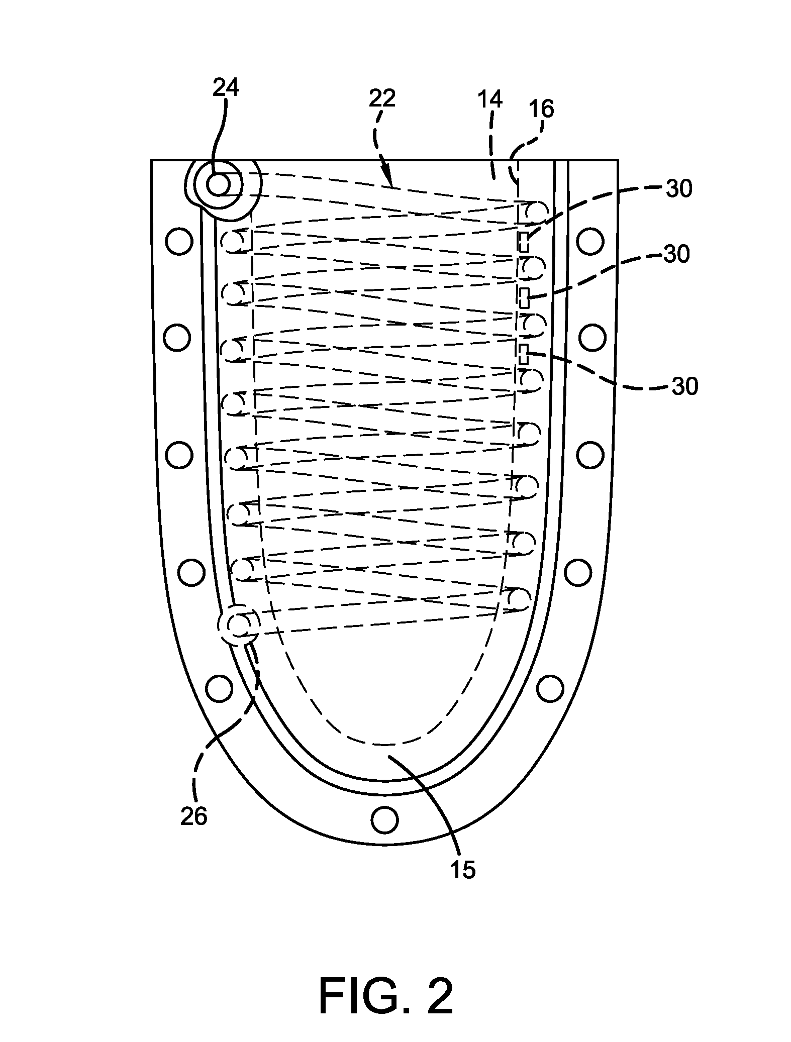
[0023]The residual limb prosthesis of the present invention further includes a coil-shaped channel 22 formed directly within the socket wall 14. The coil-shaped channel 22 extends throughout the socket wall 14 from an inlet 24 to an outlet 26, wherein the outlet 26 of the present invention fluidly communicates with the ambient atmosphere. The coil-shaped channel 22 is a continuous channel of any desired cross-sectional shape (though a circular shap...


PUM


Abstract

A residual limb prosthesis includes a socket for receiving a residual limb, the socket having a socket wall defining a limb-receiving surface. A coil-shaped channel extends through the socket wall from an inlet to an outlet, the outlet fluidly communicating with the ambient atmosphere. An air mover fluidly communicates with the inlet and the ambient atmosphere outside of the socket wall, the air mover drawing air from the ambient atmosphere and circulating the air through the coil-shaped channel to be exhausted at said outlet.

Description

CROSS-REFERENCE TO RELATED APPLICATIONS[0001]The present application claims priority to U.S. Provisional Patent Application Ser. No. 61 / 889,079, filed Oct. 10, 2013, the entirety of which is incorporated herein by reference.BACKGROUND OF THE INVENTION[0002]Many research efforts have been devoted to improving the foot, ankle, and knee units for transfemoral prosthetic components. While improving the mechanical functionality is critical, an equally important area of prosthetic design—the thermal environment—is often overlooked.[0003]Current commercially available prosthetic liners and sockets are insulators, trapping heat around the residual limb. Therefore, an unnatural environment is created around the residual limb by this trapped heat, often causing the residual limb to sweat excessively leading to numerous dermatologic conditions, such as allergic contact dermatitis, microorganism infections, and verrucous hyperplasia. Atypical loading conditions experienced by a residual limb ca...

Claims


Application Information

Patent Timeline
Patent Type & Authority Applications(United States)
IPC IPC(8): A61F2/80
CPCA61F2/80A61F2002/501A61F7/10A61F2007/0051A61F2007/0057
Inventor DAVIS, BRIAN LAWTONWEBBER, CHRISTINA MARIE
Owner THE UNIVERSITY OF AKRON
Why Eureka
Try Eureka