Display device
a technology of a display device and a display screen, which is applied in the field of display devices, can solve the problems of complicated display operation performed by users, and achieve the effect of improving user convenience and preventing operation
- Summary
- Abstract
- Description
- Claims
- Application Information
AI Technical Summary
Benefits of technology
Problems solved by technology
Method used
Image
Examples
first embodiment
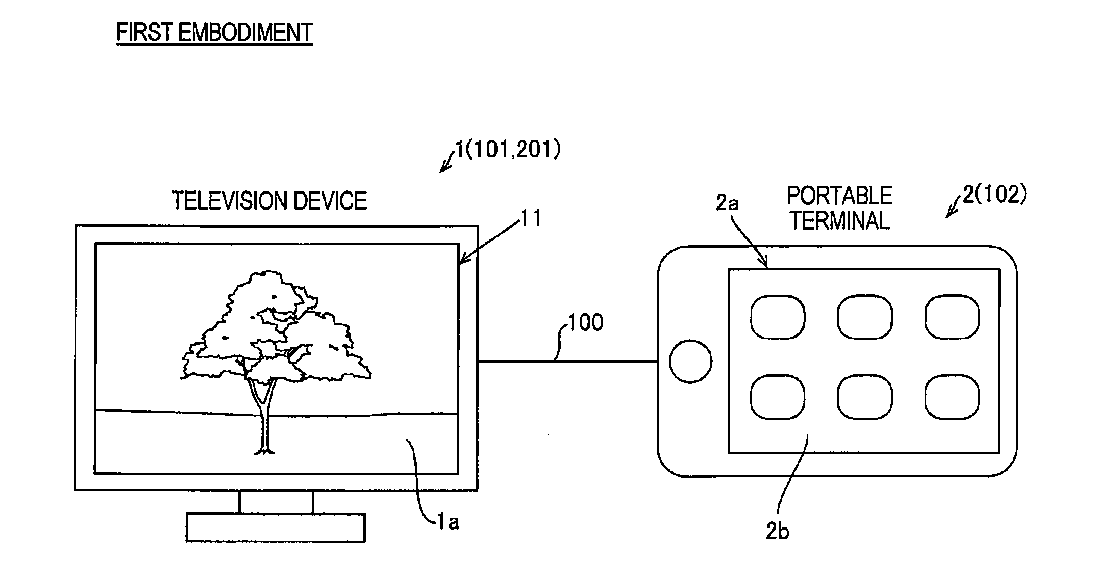
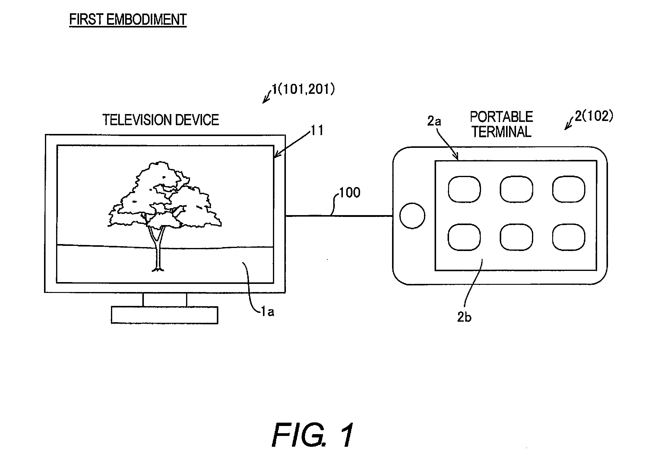
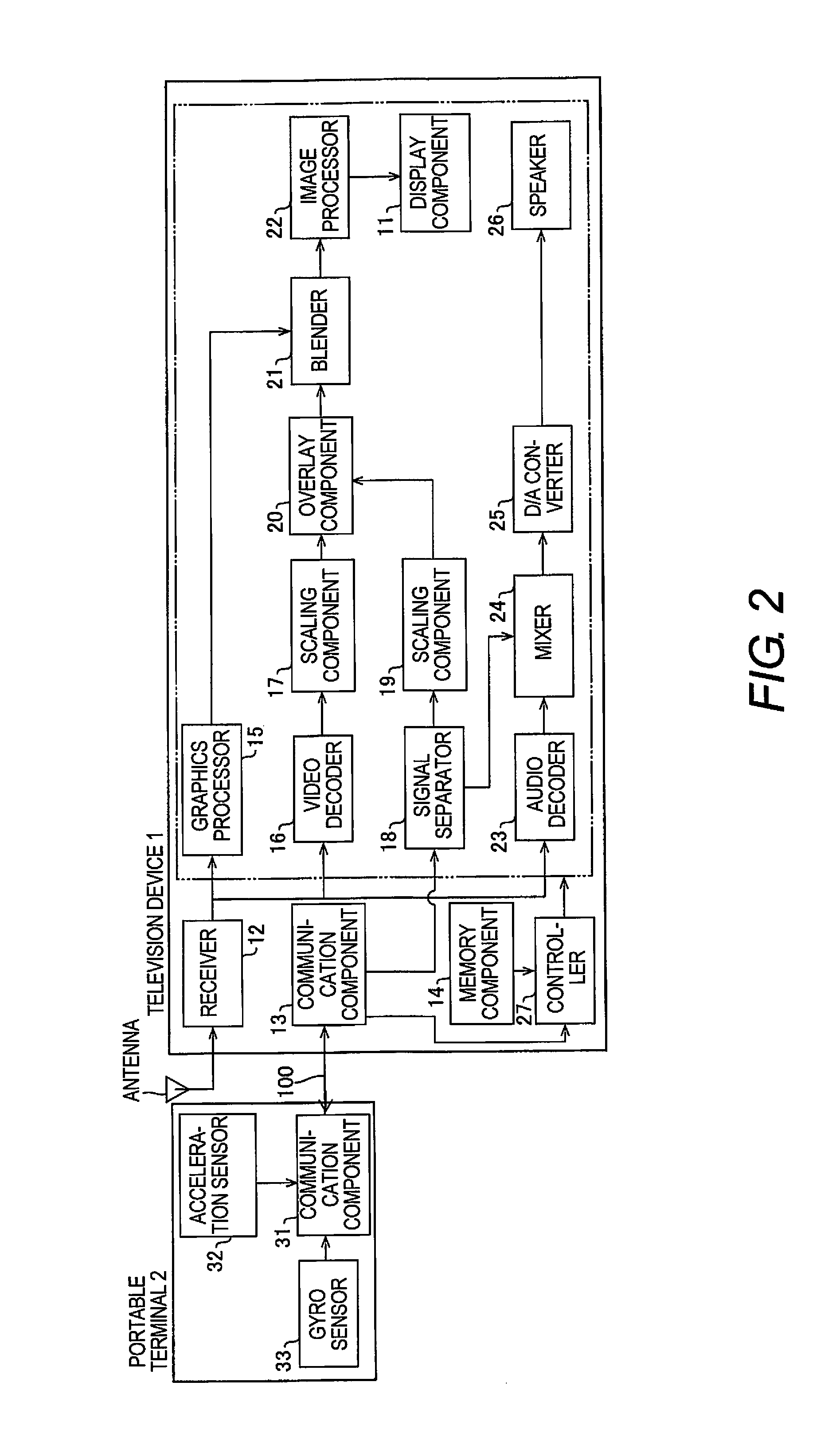
[0026]Referring initially to FIGS. 1 to 6, a television device 1 and a portable terminal 2 are illustrated in accordance with a first embodiment. The television device 1 is an example of the “display device” of the present invention.
[0027]As shown in FIG. 1, the television device 1 in accordance with the first embodiment is configured to be connected by an MHL™ (mobile high-definition link) cable 100 to a portable terminal 2 that is configured to reproduce content. MHL is an interface standard that allows two devices to be connected with a specific cable (MHL cable) capable of transmitting audio data, video data, and control signals, and thereby linking the devices together. The portable terminal 2 is a multifunction portable terminal, has a plurality of sets of content data, and has software such as a media player that can reproduce these contents. Examples of the “content” here include moving pictures taken from the Internet or an external medium, and photographs or other still pi...
second embodiment
[0070]Referring now to FIGS. 4 and 7 to 10, a television device 101 and a portable terminal 102 are illustrated in accordance with a second embodiment. In view of the similarity between the first and second embodiments, the parts of the second embodiment that are identical to the parts of the first embodiment will be given the same reference numerals as the parts of the first embodiment. Moreover, the descriptions of the parts of the second embodiment that are identical to the parts of the first embodiment may be omitted for the sake of brevity.
[0071]Basically, the television device 101 and the portable terminal 102 in accordance with the second embodiment are identical to the television device 1 and the portable terminal 2, respectively, except that the television device 101 and the portable terminal 102 respectively include GPS (global positioning system) sensors 128 and 134, and that the display image and the outputted volume are adjusted based on the relative position of the por...
third embodiment
[0090]Referring now to FIGS. 7 and 11, a television device 201 is illustrated in accordance with a third embodiment. In view of the similarity between the first to third embodiments, the parts of the third embodiment that are identical to the parts of the first and second embodiments will be given the same reference numerals as the parts of the first and second embodiments. Moreover, the descriptions of the parts of the third embodiment that are identical to the parts of the first and second embodiments may be omitted for the sake of brevity.
[0091]Basically, the television device 201 in accordance with the third embodiment is identical to the television device 101, except that the television device 201 does not have a GPS sensor.
[0092]In this third embodiment, as shown in FIG. 11, the television device 201 is configured so that a setting menu image 201b for inputting information about the current position of the television device 201 with respect to the portable terminal 102 is disp...
PUM
 Abstract
Description
Claims
Application Information
 - R&D
- Intellectual Property
- Life Sciences
- Materials
- Tech Scout
- Unparalleled Data Quality
- Higher Quality Content
- 60% Fewer Hallucinations
Browse by: Latest US Patents, China's latest patents, Technical Efficacy Thesaurus, Application Domain, Technology Topic, Popular Technical Reports.
© 2025 PatSnap. All rights reserved.Legal|Privacy policy|Modern Slavery Act Transparency Statement|Sitemap|About US| Contact US: help@patsnap.com


