Biometric information obtaining apparatus and biometric information verification apparatus

Inactive Publication Date: 2005-05-12
FUJITSU LTD
View PDF22 Cites 87 Cited by
  • Summary
  • Abstract
  • Description
  • Claims
  • Application Information

AI Technical Summary

Benefits of technology

[0017] Further, the biometric information obtaining apparatus of the present invention has an image obtaining means, a characteristic extracting means, and a relative position information detecting means, similar to the above, and the biometric information obtaining apparatus also has a correcting means (second correcting means) which corrects the position of the characteristic in the individual partial image, based on a time interval at which the image obtaining means obtains the individual partial image, on a delay in capturing the individual partial image by the image obtaining means, and on the relative position information detected by the relative position information detecting means, so that distortion of the individual partial image due to the delay in capturing the individual partial image by the image obtaining means is corrected.
[0053] (2-16) Taking an example of a sensor, such as a sweep-type biometric information sensor, which successively obtains partial images from an object (a body part of a user to be verified) that is moving with respect to the sensor surface while being in contact with the sensor surface, if the sensor is equipped with a friction reducing means for reducing friction generated by the movement of the object, it is possible to facilitate the sweep action of the body part, thereby improving user convenience. Further, since deformation of the body part is reduced, it is possible to obtain biometric information images with high reproducibility, so that verification ability is improved.

Problems solved by technology

However, since such passwords and ID cards are easily stolen, more reliable user verification (confirmation that an object user is an authorized user who has been registered beforehand) has been strongly desired.
However, since an image obtained by such a sweep-type fingerprint sensor and then reproduced is distorted due to varying factors, it is sometimes difficult to compare the fingerprint data obtained with a sweep-type fingerprint sensor and fingerprint data registered beforehand.
For example, fingerprint sensors in which a fingerprint image is obtained while a finger is moving on a sensor surface in contact with the sensor surface have the following problems.
Further, since a portion of a finger sometimes adheres to the sensor surface due to friction between the sensor surface and the finger, the finger is deformed, whereby a large distortion is caused in a resulting fingerprint image.
Further, as shown in FIG. 19 through FIG. 26, if an image-capturing device, which obtains an image of a fingerprint, has any detection delay, captured images are distorted irrespective of distortion of the finger itself.
Taking an example of a sensor in which information is detected by one scanning line, and information is detected by the adjacent scanning line after elapse of a specific delay, (see FIG. 25), if relative position information between a finger and the sensor is greatly changed over time, an aspect ratio of a captured fingerprint image is changed, thereby causing an extractive / contractive distortion (see FIG. 21 through FIG. 24).
Further, in a sensor in which detection delay appears for each cell (see FIG. 26), a skew distortion occurs (see FIG. 25 and FIG. 26).
Such distortion deteriorates the reproducibility of a reproduced image.
That is, characteristic information obtained from a user with a fingerprint sensor is significantly different from the user's registered characteristic information because of the distortion described above or the appearance of patterns that do not exist in a fingerprint.
Thus, a false verification result could be obtained even if an object user to be verified is an authorized user, so that verification ability, that is, verification reliability, is deteriorated.
Further, in the techniques disclosed in the above Japanese patent applications and in the above U.S. patents, the following problems are also caused.
Thus, the above techniques are not applicable to small-sized information equipment.

Method used


Image

  • Biometric information obtaining apparatus and biometric information verification apparatus
  • Biometric information obtaining apparatus and biometric information verification apparatus
  • Biometric information obtaining apparatus and biometric information verification apparatus

Examples


Embodiment Construction

[0087] One preferred embodiment of the present invention will now be described with reference to the relevant accompanying drawings.

[0088] [1] Verification Apparatus of the Present Embodiment

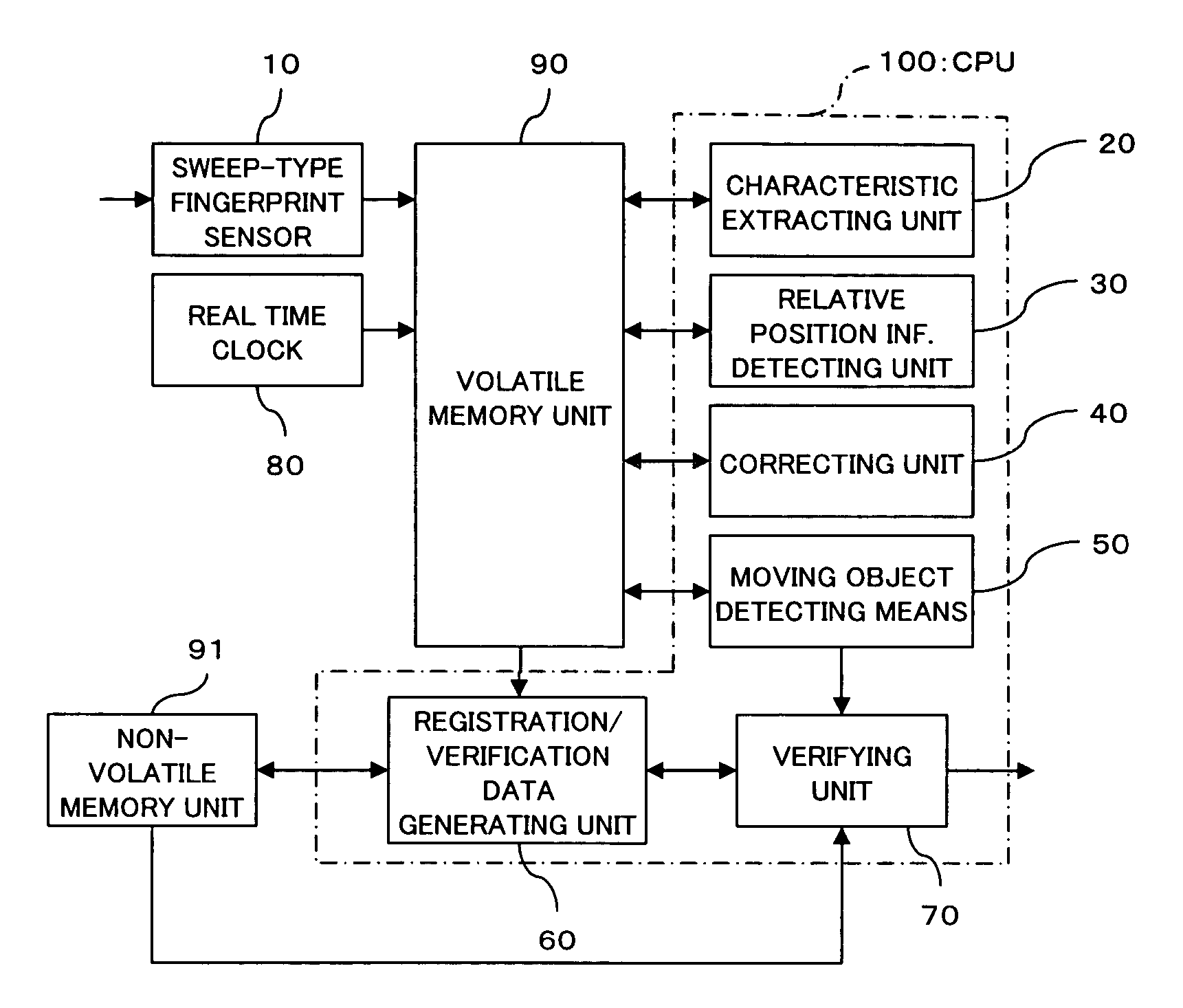
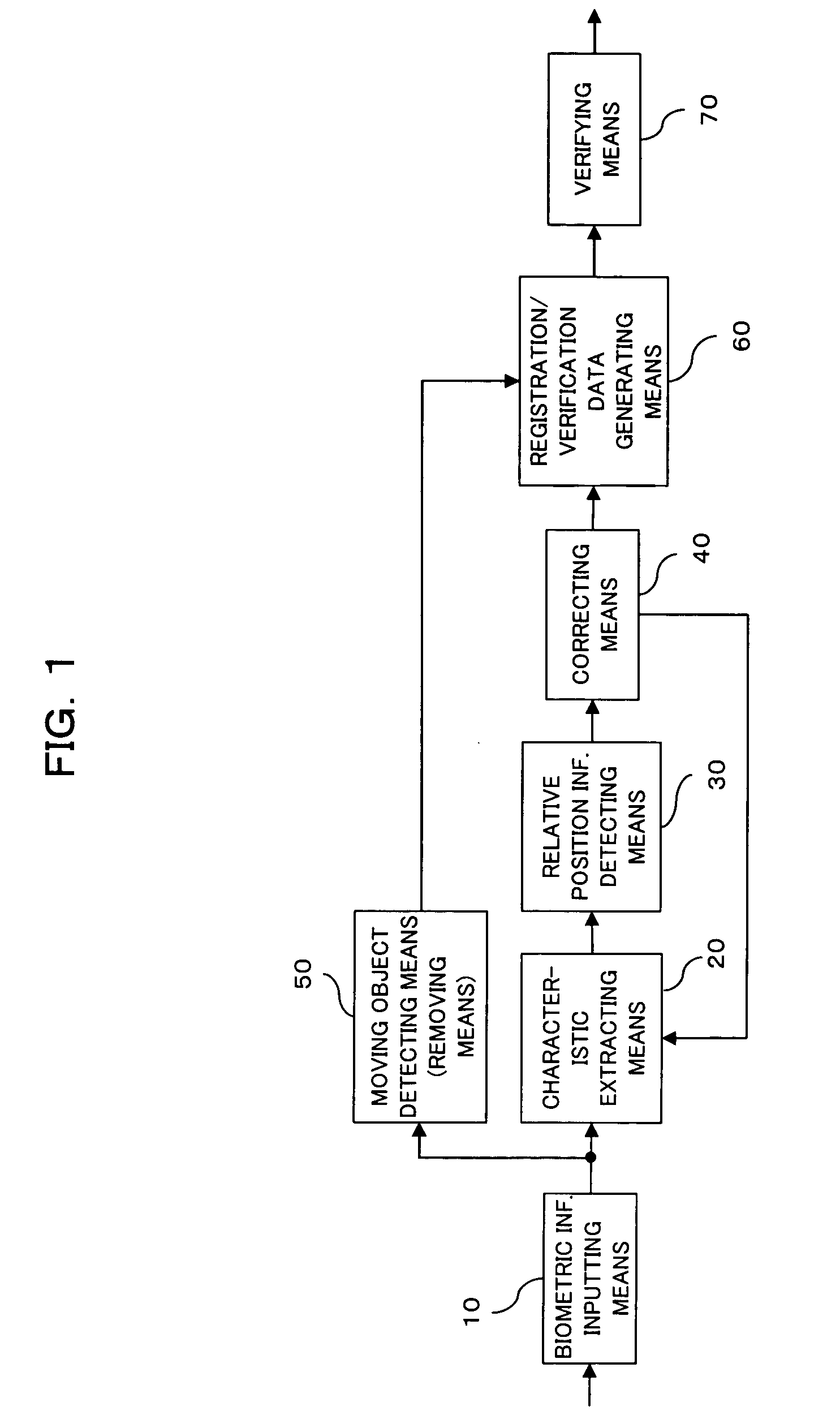
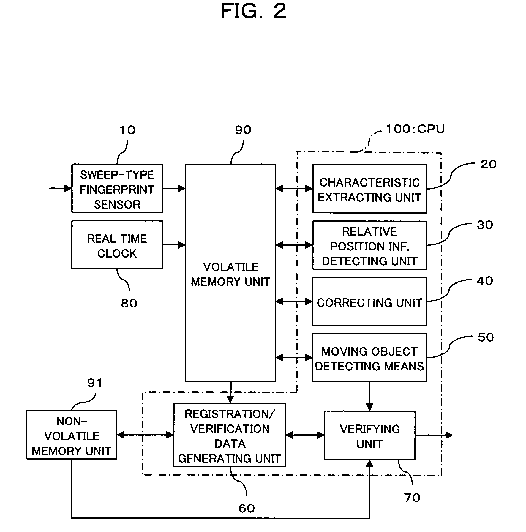
[0089] Both FIG. 1 and FIG. 2 show a construction of a biometric user verification apparatus (biometric information obtaining apparatus) according to one preferred embodiment of the present invention. FIG. 1 is a block diagram showing a functional construction (principle construction) of a biometric verification apparatus according to one preferred embodiment of the present invention. FIG. 2 is a block diagram showing a specific construction of the biometric verification apparatus. In FIG. 1 and FIG. 2, like reference numbers and characters designate similar parts or elements.

[0090] As shown in FIG. 1, the verification apparatus of the present embodiment has functions as a biometric information inputting means (image obtaining means) 10, a characteristic extracting means 20, a relative positi...


PUM


Abstract

The object is to obtain undistorted images in high speed using a small amount of memory capacity, to realize high-quality characteristic information verification. The apparatus, which obtains information needed for user verification from partial images that are successively captured by a sweep-type fingerprint sensor from a fingertip, includes image obtaining means which captures successive partial images of biometric information; characteristic extracting means which obtains, from the captured partial images, characteristics and positions of the characteristics; detecting means which detects relative position information of partial images based on characteristics contained in a region in which the partial images overlap; and correcting means which calculates the amount of distortion of the characteristics based on the detected relative position information and on the positions of the characteristics in each partial image, and which corrects the positions of the characteristics in each individual partial image based on the calculated distortion amount.

Description

BACKGROUND OF THE INVENTION [0001] 1. Field of the Invention [0002] The present invention relates to an apparatus for obtaining biometric information such as fingerprints, palm prints, and blood vessel patterns. The invention relates particularly to a biometric information obtaining apparatus which obtains information needed for user verification from partial images (fingerprint images) that are successively obtained while a finger is moving relative to the sensor surface (image capturing surface) of a sweep-type fingerprint sensor. Further, the present invention relates to a verification apparatus on which user verification is performed using biometric information such as fingerprints, palm prints, and blood vessel patterns. [0003] 2. Description of the Related Art [0004] With recent improvement in functionality, small-sized information equipment, such as mobile phones and PDAs (Personal Digital Assistants), is capable of connecting to communication networks and storing a great amo...

Claims


Application Information

Patent Timeline
IPC IPC(8): A61B5/117G01B7/28G06K9/00G06T1/00
CPCG06K9/00026G06V40/1335
Inventor ABIKO, YUKIHIROFUJII, YUSAKUMORIHARA, TAKASHI
Owner FUJITSU LTD
Why Eureka
Try Eureka