

Image display method and apparatus
- Summary
- Abstract
- Description
- Claims
- Application Information
AI Technical Summary
Benefits of technology
Problems solved by technology
Method used
Image

Examples
Embodiment Construction
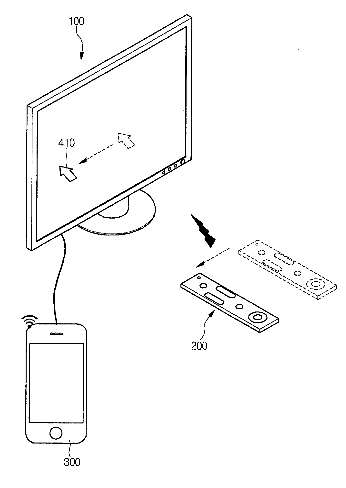
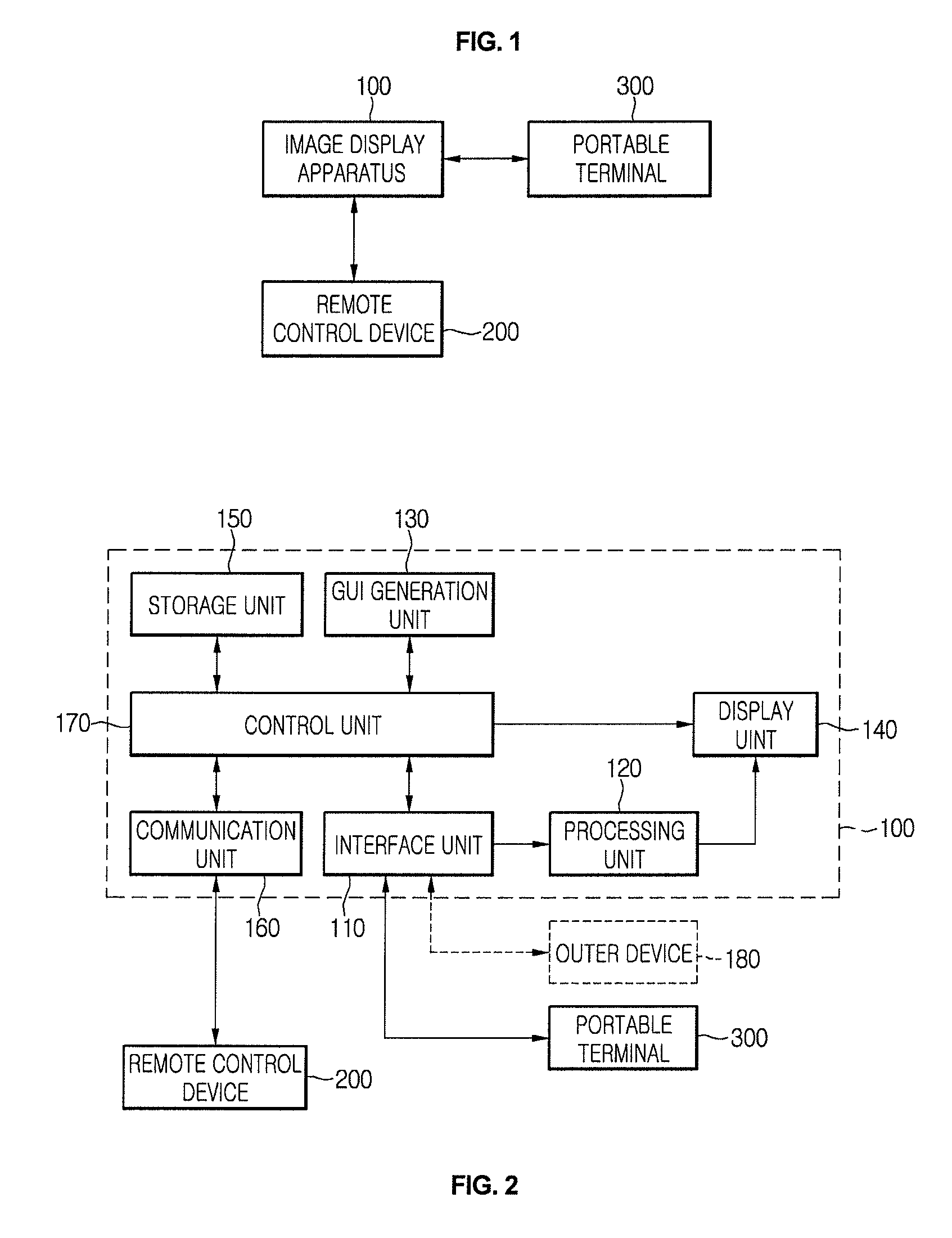
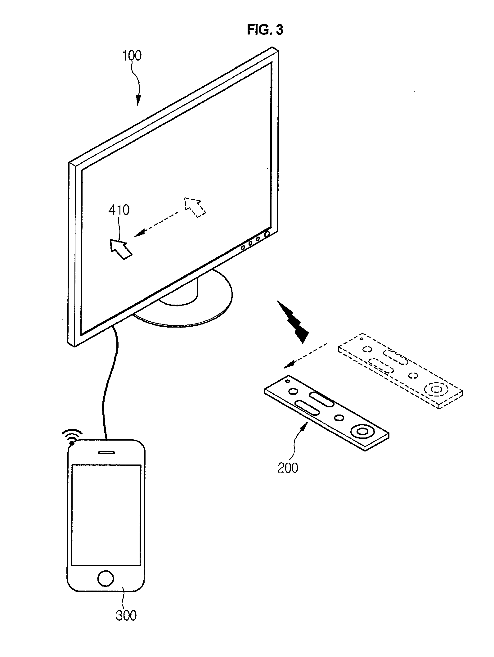
[0038]Hereinafter, an image display apparatus and method according to an embodiment of the present invention will be described with reference to the accompanying drawings in detail.
[0039]Furthermore, although the embodiments of the present invention will be described with reference to the accompanying drawings, but the present invention is not restricted or limited by the embodiments.
[0040]Terminology used in the specification of the present invention may adapt common technical terminology that is well-known broadly in consideration of the functions of the present invention and it may be varied according to purpose or practices of people who pertain to the art. In addition, terms randomly selected by the applicant are used in specific case, and in this case, its meaning will be described in the corresponding description of the embodiments of the invention. Therefore, the terms used in the specification may be understood as the meaning based on the content of the description, not as ...
PUM
 Abstract
Description
Claims
Application Information