Method and apparatus for generating a digital signal of tunable frequency and frequency synthesizer employing same

Inactive Publication Date: 2015-04-23
EUROPEAN SPACE AGENCY
View PDF2 Cites 5 Cited by
  • Summary
  • Abstract
  • Description
  • Claims
  • Application Information

AI Technical Summary

Benefits of technology

The patent describes a method for generating a tunable digital signal with a low spur content. The method allows for the adjustment of the frequency of the digital signal through a mechanism called a fractional-N divider, which can be controlled using a variable control value. By setting the division ratio of the fractional-N divider to spur-free values, a high degree of flexibility in the frequency adjustment can be achieved without the need for additional up-multiplication of the input signal. The technical effect of this method is a more efficient and flexible way to generate tunable digital signals with minimal spur content.

Problems solved by technology

With a fractional-N frequency synthesizer as described above, however, the problem occurs that the two signals that are compared at the PFD are never exactly in phase.
However, on occurrence of a flip of polarity of the current, the current is momentarily very small, and due to the characteristics of the charge pump 104 the magnitude of the current changes non-linearly in this regime.
Also, the time dependence of the output current is unpredictable in this case.
However, neither of these mechanisms is known to completely remove fractional spurs.
Also, especially for fractional-N frequency synthesizers implemented on a single chip, means for reducing the level of fractional spurs are limited due to design considerations and space limitations.
However, reducing the level of fractional spurs by means of a phase interpolation divider will increase phase noise, and active loop filtering is required.
However, due to sampling errors and digital-to-analog conversion, the output signal of the DDS is not spur-free.

Method used


Image

  • Method and apparatus for generating a digital signal of tunable frequency and frequency synthesizer employing same
  • Method and apparatus for generating a digital signal of tunable frequency and frequency synthesizer employing same
  • Method and apparatus for generating a digital signal of tunable frequency and frequency synthesizer employing same

Examples


first embodiment

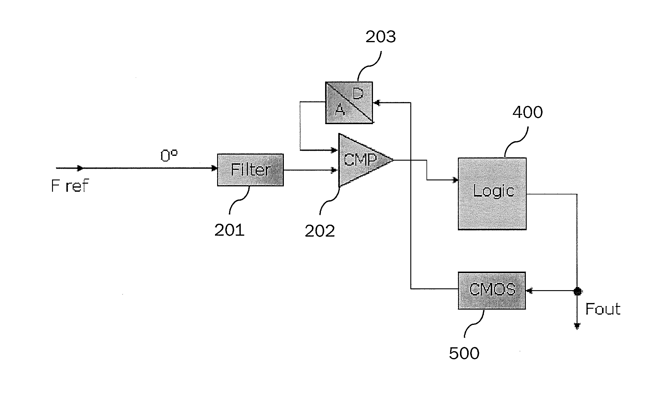
[0057]FIG. 2 illustrates a signal generator for generating a signal having a tunable frequency according to the invention. The signal generator comprises a filter 201 (first filter), a comparator 202 (first comparator), a digital-to-analog converter 203 (first digital-to-analog converter), a logic module 400 and a controller 500. A reference frequency Fref of a digital reference signal that is e. g. generated by an oscillating crystal is fed to the filter 201. The reference signal is a digital signal, such as a rectangular signal. For exemplary purposes, the reference frequency Fref is assumed to be 100 MHz. The filter 201 is an integrator, and may comprise a capacitor (first capacitor) connected to a current source (first current source) for charging the capacitor with a constant current. The comparator 202 preferably represents an analog level trigger.

[0058]As will be described with reference to FIGS. 3, 4A, and 4B, integration by the filter 201 is triggered by a transition (switc...

second embodiment

[0094]FIG. 5 illustrates a signal generator for generating a digital signal of tunable frequency according to the invention. In addition to a first reference branch formed by the first filter 201, the first comparator 202 and the first digital-to-analog converter 203, the signal generator of FIG. 5 also comprises a second reference branch. Like-numbered elements in FIGS. 2 and 5 are understood to be identical in configuration as well as in function, unless indicated otherwise. The first filter 201, the first comparator 202, and the first digital-to-analog converter 203 are identical to the like-numbered elements in FIG. 2. The second reference branch is formed by a NOT-gate 305 which serves as a phase shifter, a second filter 301, a second comparator 302, and a second digital-to-analog converter 303.

[0095]The reference signal Fref is fed to the phase shifter 305, in which the high levels of the reference signal are transformed into low levels and vise versa. If the reference signal ...


PUM


Abstract

A method for generating a digital signal of tunable frequency may include generating a periodic first analog signal, determining a sign of a first difference between a value of the first analog signal and a first control value to determine sign flips, wherein the first control value is a variable value, and generating the digital signal of tunable frequency on the basis of the determined sign of the first difference, wherein the digital signal of tunable frequency is generated such that a subset of switches of the signal level are coincident with a respective sign flip of the determined sign of the first difference.

Description

TECHNICAL FIELD OF THE INVENTION[0001]The present invention relates to a method and an apparatus for generating a digital signal of tunable frequency, such as a reference clock signal of tunable frequency.[0002]The invention is particularly though not exclusively applicable to generating a reference clock signal for a fractional-N frequency synthesizer and to operating a fractional-N frequency synthesizer on the basis of the reference clock signal.BACKGROUND OF THE INVENTION[0003]Frequency synthesizers are commonly used to generate signals of a desired frequency, e. g. in the field of terrestrial communication or satellite communication. A widespread type of a frequency synthesizer is a fractional-N phase lock loop (PLL) frequency synthesizer, which allows for a very high frequency resolution. A typical configuration of such a fractional-N frequency synthesizer is illustrated in FIG. 1. The fractional-N frequency synthesizer 100, according to FIG. 1 comprises a reference clock gener...

Claims


Application Information

Patent Timeline
IPC IPC(8): H03L7/197H03L7/097
CPCH03L7/097H03L7/1974
InventorLIA, ENRICOLAUER, ANDREASKOETHER, DIETMARFOLLMANN, RUDIGER
OwnerEUROPEAN SPACE AGENCY