Ceramic electronic component

a technology of ceramic electronic components and components, applied in the direction of fixed capacitor details, stacked capacitors, fixed capacitors, etc., can solve the problems of cracks in ceramic bodies, and achieve the effect of significantly reducing or preventing cracks

Active Publication Date: 2015-04-30
MURATA MFG CO LTD
View PDF6 Cites 18 Cited by
  • Summary
  • Abstract
  • Description
  • Claims
  • Application Information

AI Technical Summary

Benefits of technology

[0013]A preferred embodiment of the present invention provides a ceramic electronic component in which the occurrence of cracks is significantly reduced or prevented.

Problems solved by technology

A multilayer ceramic capacitor in which a stress is accumulated in outer electrodes may experience changes in external environment such as changes in temperature, which may cause a crack to occur in the ceramic body due to the stress accumulated in the outer electrode.

Method used


Image

  • Ceramic electronic component
  • Ceramic electronic component
  • Ceramic electronic component

Examples


Embodiment Construction

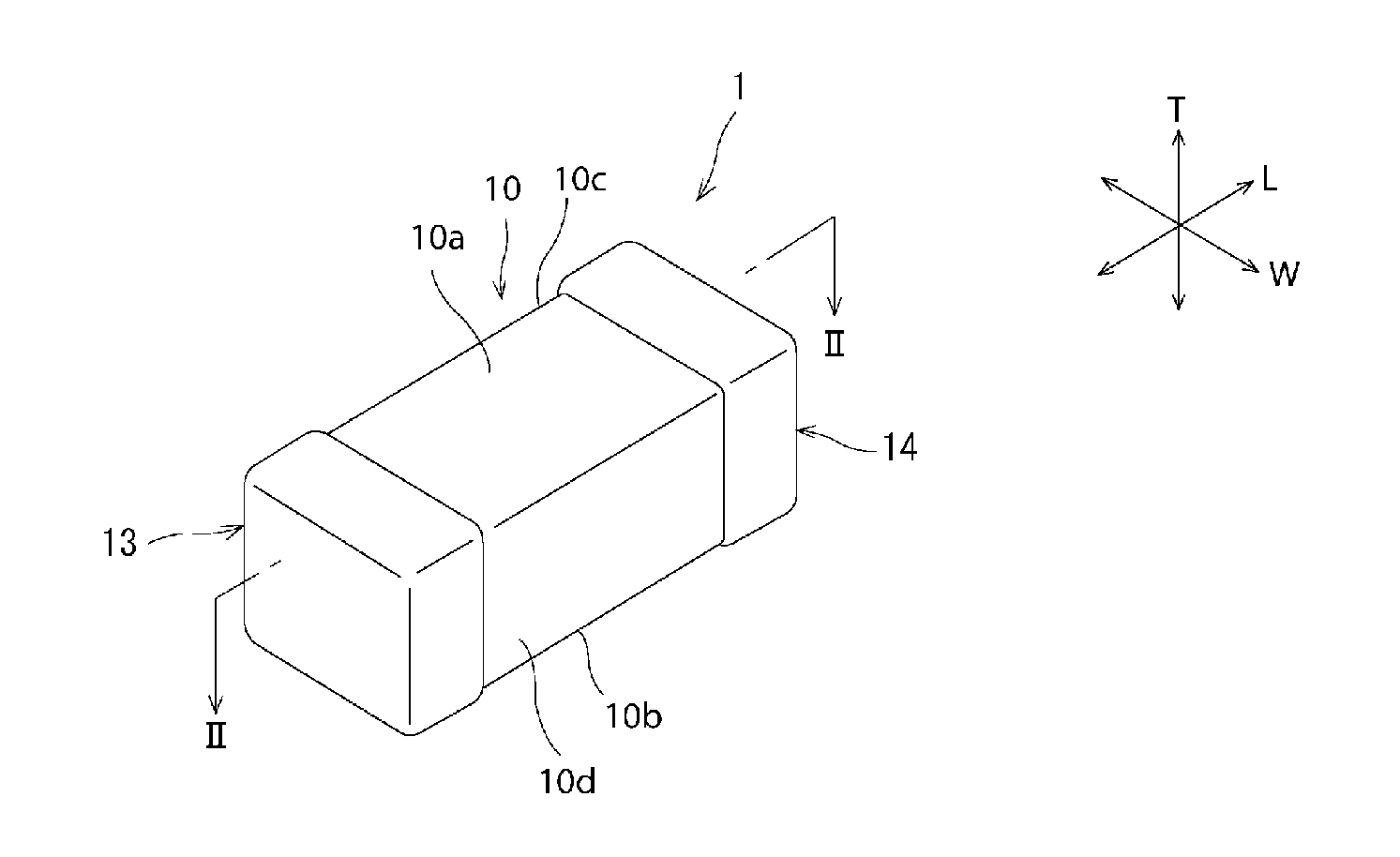
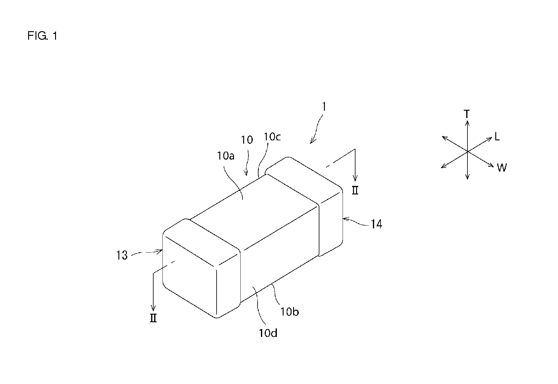
[0018]Examples of preferred embodiments of the present invention will be described hereinafter. The following preferred embodiments are merely non-limiting examples. The present invention is not limited to the following preferred embodiments.

[0019]In the drawings that will be referred to in the following preferred embodiments and the like, members having the same or substantially the same function will be referred to by the same reference signs. In addition, the drawings that will be referred to in the following preferred embodiments and the like are schematically illustrated. The dimensional ratios and the like of objects illustrated in the drawings may sometimes be different from the actual dimensional ratios and the like of the objects. The dimensional ratios and the like of the objects may also sometimes differ between the drawings. The specific dimensional ratios and the like of the objects should be determined by taking the following description into consideration.

[0020]A cera...


PUM

PropertyMeasurementUnit
thicknessaaaaaaaaaa
widthaaaaaaaaaa
widthaaaaaaaaaa

Abstract

A ceramic electronic component includes a first fired electrode layer disposed on top of a ceramic body. The first fired electrode layer includes first to fifth portions that are separate from each other. The first portion is disposed on top of a first end surface. The second portion is disposed on top of a first principal surface. The third portion is disposed on top of a second principal surface. The fourth portion is disposed on top of a first side surface. The fifth portion is disposed on top of a second side surface.

Description

BACKGROUND OF THE INVENTION[0001]1. Field of the Invention[0002]The present invention relates to a ceramic electronic component.[0003]2. Description of the Related Art[0004]In the related art, a multilayer ceramic electronic component includes outer electrodes that cover end surfaces of a ceramic body (see, for example, Japanese Unexamined Patent Application Publication No. 2013-89946). Each of the outer electrodes extends from the corresponding one of the end surfaces of the ceramic body onto first and second principal surfaces and first and second side surfaces.[0005]The outer electrodes that cover the end surfaces of the ceramic body are typically formed by applying conductive paste to the end surfaces of the ceramic body and then performing a heat treatment on the conductive paste. When the heat treatment is performed, a stress is accumulated in the outer electrodes due to the difference in coefficient of linear expansion between the ceramic body and the outer electrodes. A mult...

Claims


Application Information

Patent Timeline
Patent Type & Authority Applications(United States)
IPC IPC(8): H01G4/30H01G4/248H01G4/005H01G4/12
CPCH01G4/30H01G4/005H01G4/248H01G4/12H01G4/0085H01G4/232H10N30/8554H01C7/008H01F27/2804H01F27/292H01F2027/2809H01G4/1272H01G4/228
Inventor SASAOKA, YOSHIKAZU
Owner MURATA MFG CO LTD
Why Eureka
Try Eureka