

Extendable slide member for pistol slide
- Summary
- Abstract
- Description
- Claims
- Application Information
AI Technical Summary
Benefits of technology
Problems solved by technology
Method used
Image

Examples
Embodiment Construction
)
[0053]In describing the preferred embodiment of the present invention, reference will be made herein to FIGS. 1-12 of the drawings in which like numerals refer to like features of the invention.
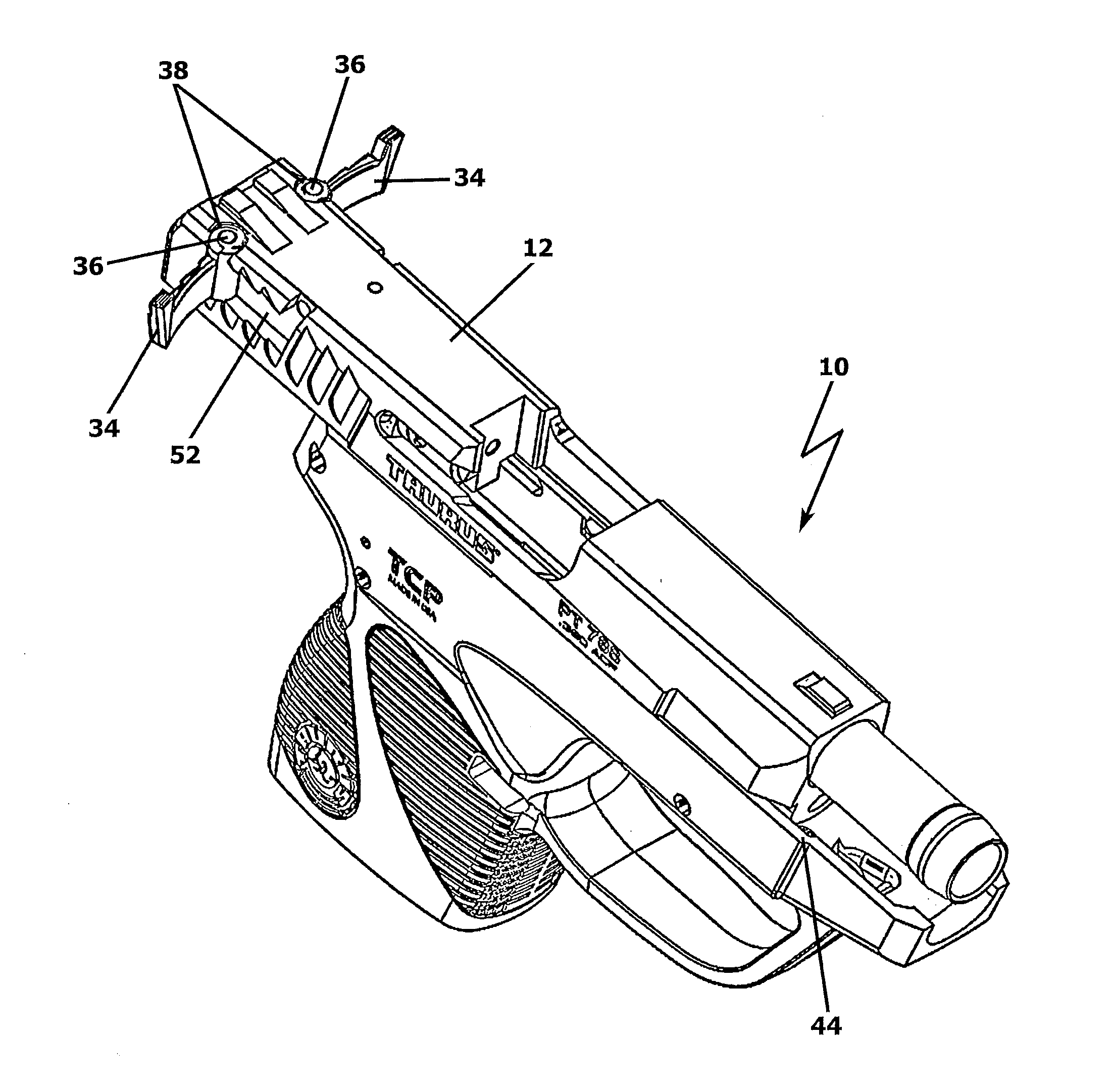
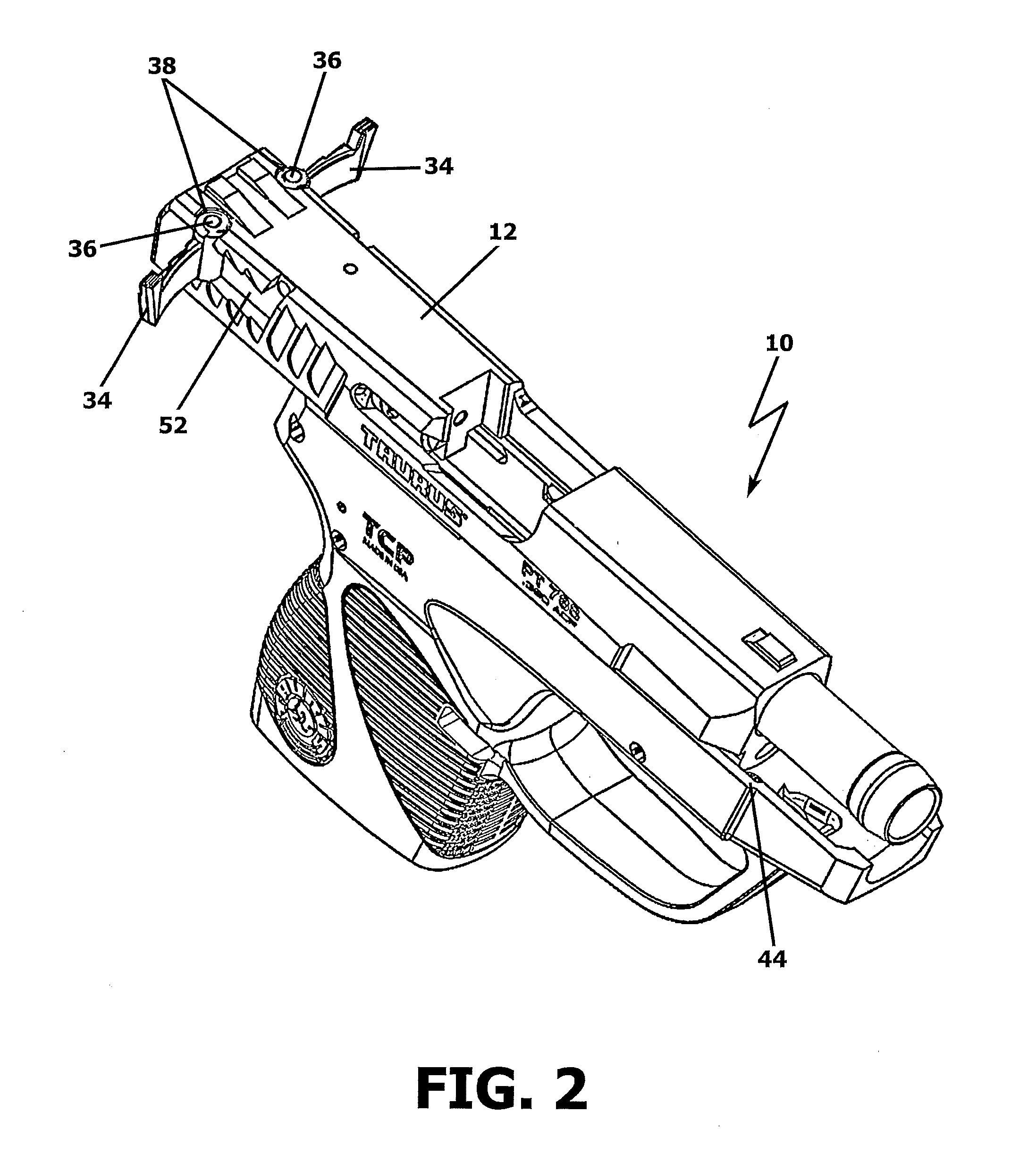
[0054]In one embodiment, the present invention introduces an extendable slide member on at least one side of a pistol slide action, and preferably on both sides of a pistol slide action that provides leverage and a gripping base for a user to pull back or “rack” the slide along guides on a pistol frame, in a longitudinal motion relative to the pistol frame.
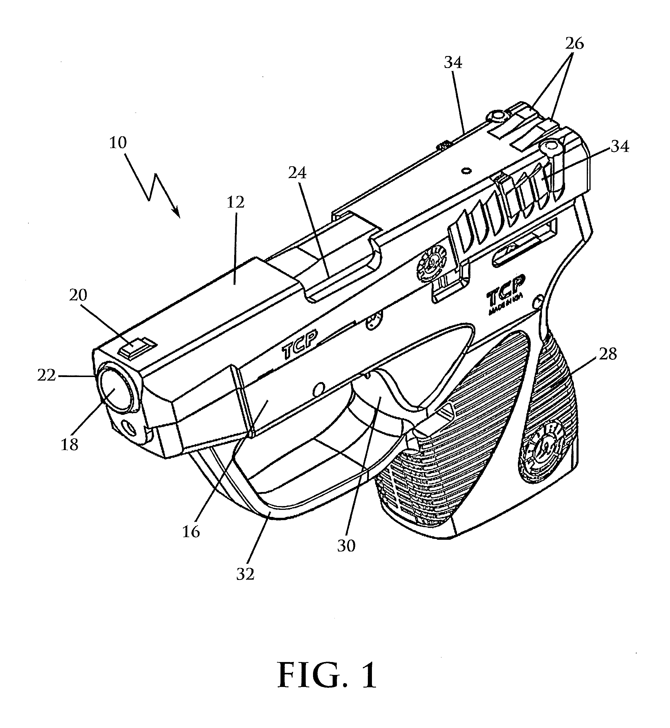
[0055]FIG. 1 is a top perspective view of a pistol 10 having a slide 12 embodying slide members 34 of the present invention. Slide 12 is slidably engaged on guide rails (not shown) and movable longitudinally in relation to frame 16 (along the axis of the barrel). In the FIG. 1 configuration, slide 12 is in a forward position, before a user retracts or racks the slide to load a cartridge into the chamber. Slide 12 is biased in the forward p...
PUM
 Abstract
Description
Claims
Application Information