Force detecting device, robot, electronic component conveying apparatus

Active Publication Date: 2015-05-07
SEIKO EPSON CORP
View PDF30 Cites 21 Cited by
  • Summary
  • Abstract
  • Description
  • Claims
  • Application Information

AI Technical Summary

Benefits of technology

[0088]With this configuration, since the weight of the force detecting device can be set smaller than 20% of the maximum weight that the

Problems solved by technology

However, in the force measuring device including the quartz as the piezoelectric element, the quartz is deformed by heat generated dur

Method used


Image

  • Force detecting device, robot, electronic component conveying apparatus
  • Force detecting device, robot, electronic component conveying apparatus
  • Force detecting device, robot, electronic component conveying apparatus

Examples


first embodiment

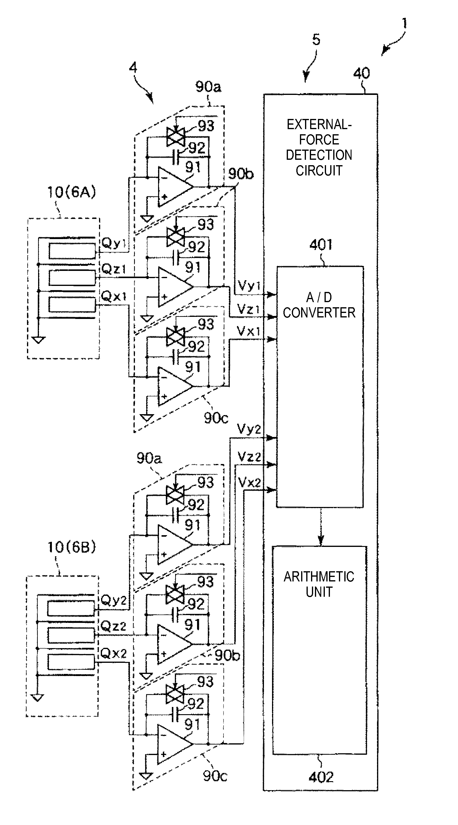
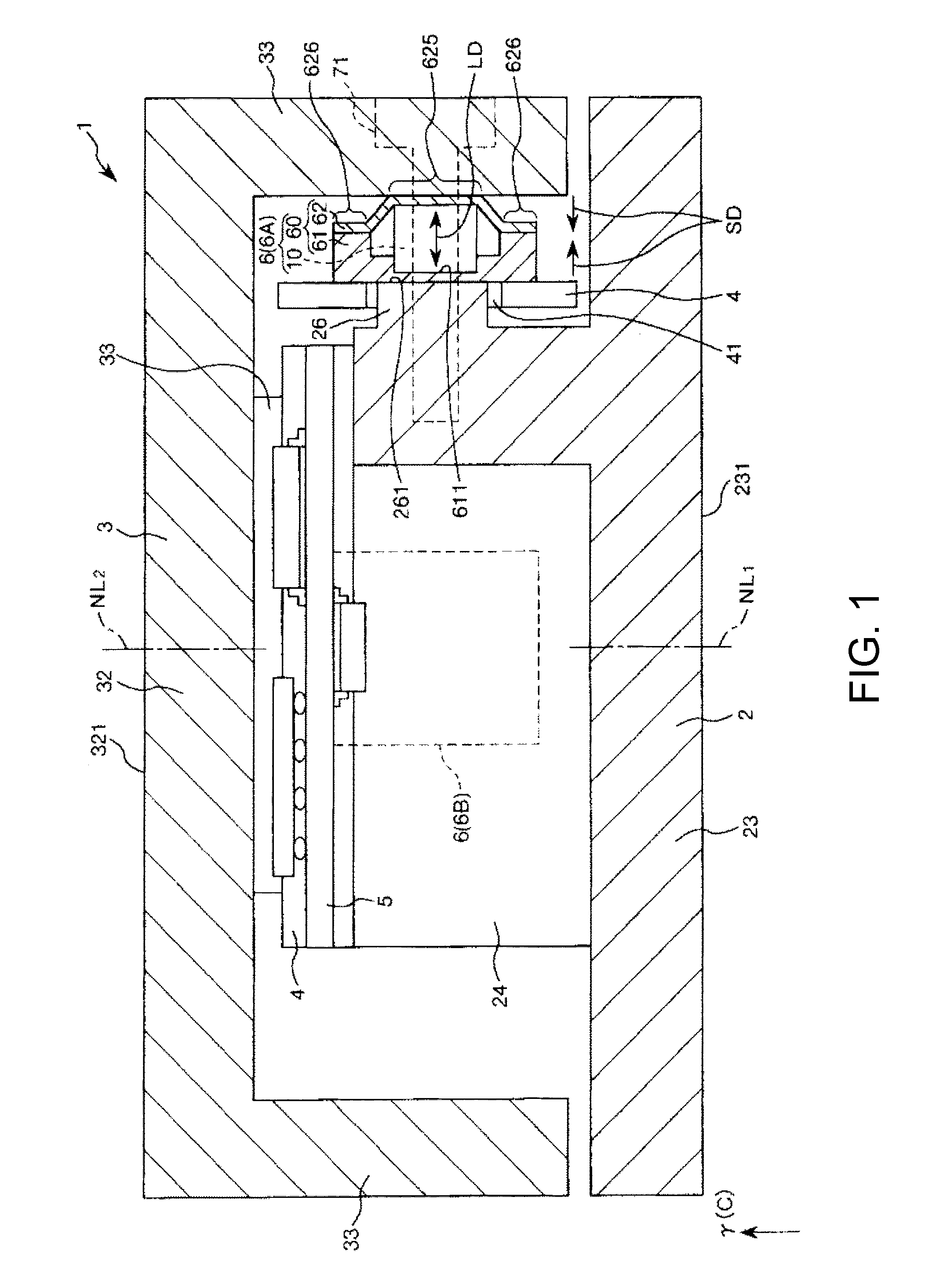
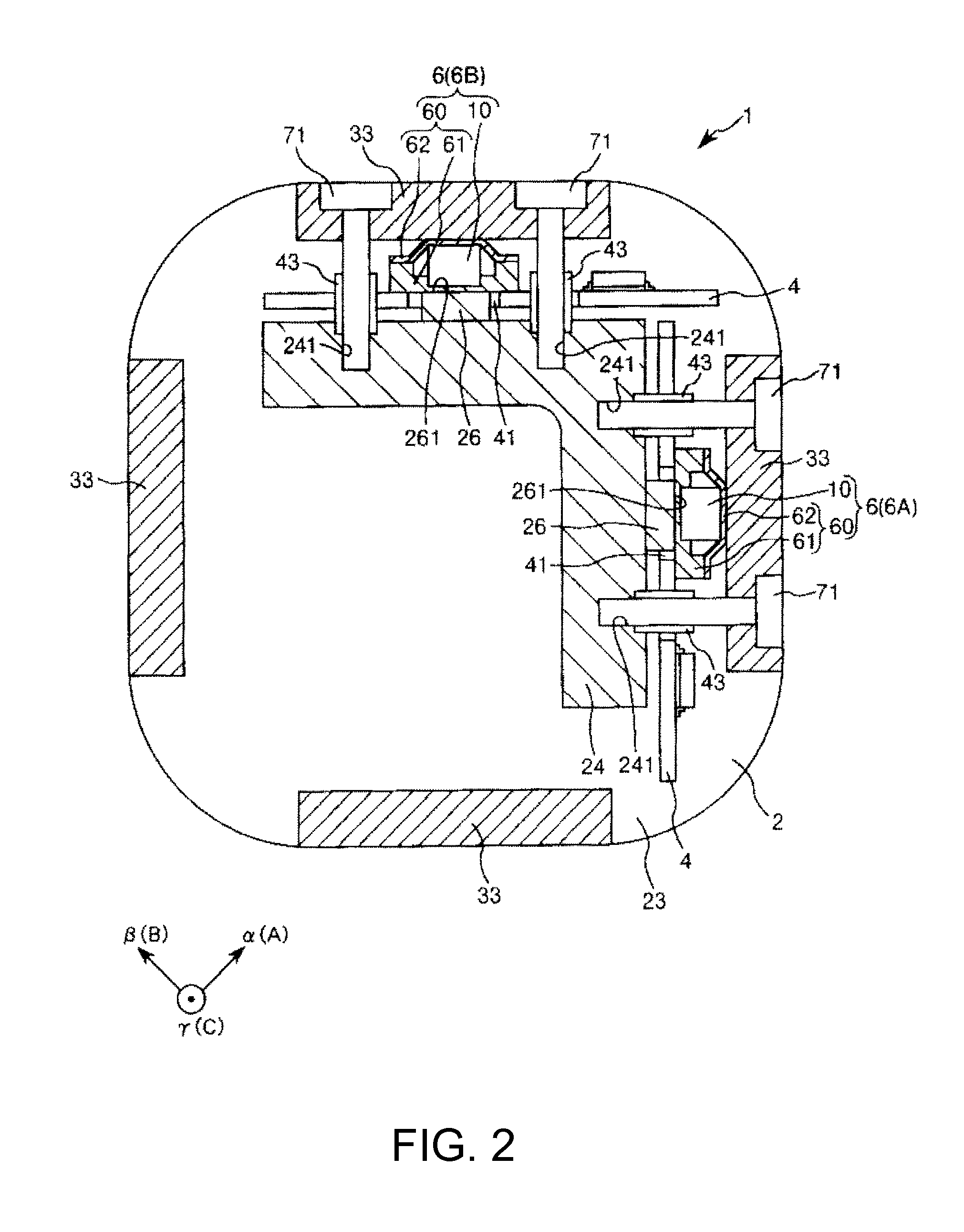
[0120]FIG. 1 is a sectional view showing a force detecting device according to a first embodiment of the invention. FIG. 2 is a plan view of the force detecting device shown in FIG. 1. FIG. 3 is a circuit diagram schematically showing the force detecting device shown in FIG. 1. FIG. 4 is a sectional view schematically showing a charge output element of the force detecting device shown in FIG. 1. FIG. 5 is a schematic diagram showing an action state of a force detected by a charge output element of the force detecting device shown in FIG. 1. FIG. 6 is a diagram of the charge output element viewed from an arrow A direction in FIG. 5.

[0121]Note that, in the following explanation, for convenience of explanation, the upper side in FIG. 1 is referred to as “up” or “upward” and the lower side in the figure is referred to as “down” or “downward”.

[0122]A force detecting device 1 shown in FIGS. 1 and 2 has a function of detecting an external force (including a moment), that is, a function of ...

second embodiment

[0204]FIG. 7 is a sectional view showing a force detecting device according to a second embodiment of the invention. FIG. 8 is a plan view of the force detecting device shown in FIG. 7. FIG. 9 is a circuit diagram schematically showing the force detecting device shown in FIG. 7.

[0205]A force detecting device, a robot, and an electronic component conveying apparatus according to the second embodiment of the invention are explained below with reference to the drawings. Differences from the first embodiment are mainly explained below. Explanation of similarities is omitted.

[0206]This embodiment is the same as the first embodiment except that the number of arranged sensor devices is different.

[0207]As shown in FIGS. 7 and 8, in this embodiment, four sensor devices 6 (charge output elements 10) are set. In the following explanation, the sensor devices 6 are referred to as “sensor device (first sensor element) 6A”, “sensor device (second sensor element) 6B”, “sensor device (third sensor e...

third embodiment

[0213]FIG. 10 is a sectional view showing a force detecting device according to a third embodiment of the invention. FIG. 11 is a circuit diagram schematically showing the force detecting device shown in FIG. 10. FIG. 12 is a sectional view schematically showing a charge output element of the force detecting device shown in FIG. 10. FIG. 13 is a schematic diagram showing an action state of a force detected by the charge output element of the force detecting device shown in FIG. 10. FIG. 14 is a diagram of the charge output element viewed from an arrow A direction in FIG. 13.

[0214]Note that, in the following explanation, for convenience of explanation, the upper side in FIG. 10 is referred to as “up” or “upward” and the lower side in the figure is referred to as “down” or “downward”.

[0215]A force detecting device 1001 shown in FIG. 10 has a function of detecting an external force (including a moment), that is, a function of detecting external forces applied along three axes (an α (A)...


PUM


Abstract

A force detecting device includes a first base section, a second base section, and a charge output element arranged between the first base section and the second base section. The charge output element includes a first board formed by a Y-cut quartz plate and a second board formed by a Y-cut quartz plate. The boards are laminated in a direction orthogonal to the normal an attachment surface of the second base section. The force detecting device detects an external force on the basis of a first output corresponding to a shearing force in a first detection direction orthogonal to the laminating direction of the first board and a second output corresponding to a shearing force in a second detection direction orthogonal to the laminating direction of the second board and crossing the first detection direction.

Description

BACKGROUND[0001]1. Technical Field[0002]The present invention relates to a force detecting device, a robot, and an electronic component conveying apparatus.[0003]2. Related Art[0004]In recent years, for the purpose of improvement of productivity, industrial robots have been introduced into production facilities such as factories. A representative example of such an industrial robot is a machine tool that applies machining to a base material such as an aluminum plate. Some machine tool incorporates a force detecting device that detects a force imposed on the base material when the machining is applied thereto (see, for example, JP-A-10-68665 (Patent Literature 1)).[0005]The force measuring device (the force detecting device) described in Patent Literature 1 can detect a shearing force, a tensile force, a compressive force, and the like using quartz functioning as a piezoelectric element.[0006]However, in the force measuring device including the quartz as the piezoelectric element, th...

Claims


Application Information

Patent Timeline
IPC IPC(8): B25J9/16
CPCB25J9/1694G01L5/167G01L5/226G01P15/18H02N2/0095G01P15/09Y10S901/46H10N30/802H10N30/50H10N30/302B25J9/1633B25J13/085G01L1/16G01L1/18G01L5/00G01L5/009
Inventor KAMIYA, TOSHIYUKIKAWAI, HIROKI
Owner SEIKO EPSON CORP
Why Eureka
Try Eureka