Systems and methods for keyed welding clamp

a technology of keyed welding and system methods, which is applied in the direction of soldering apparatus, manufacturing tools,auxillary welding devices, etc., can solve the problem of difficulty in mounting an orbital welding track on the workpi

Inactive Publication Date: 2015-05-14
LINCOLN GLOBAL INC
View PDF0 Cites 6 Cited by
  • Summary
  • Abstract
  • Description
  • Claims
  • Application Information

AI Technical Summary

Problems solved by technology

In some specific instances, the work piece size, geometry, or other configurations make it difficult to mount an orbital welding track on the work piece.

Method used


Image

  • Systems and methods for keyed welding clamp
  • Systems and methods for keyed welding clamp
  • Systems and methods for keyed welding clamp

Examples


Embodiment Construction

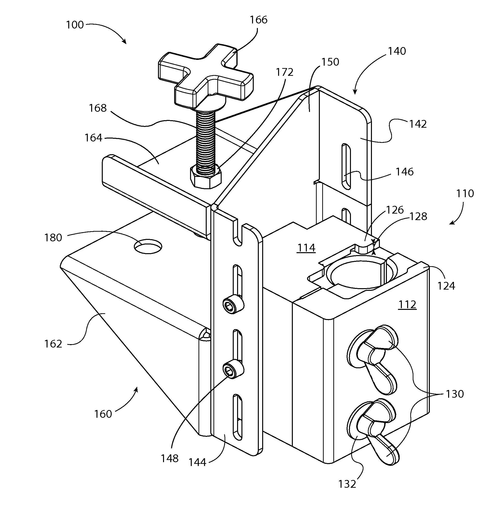
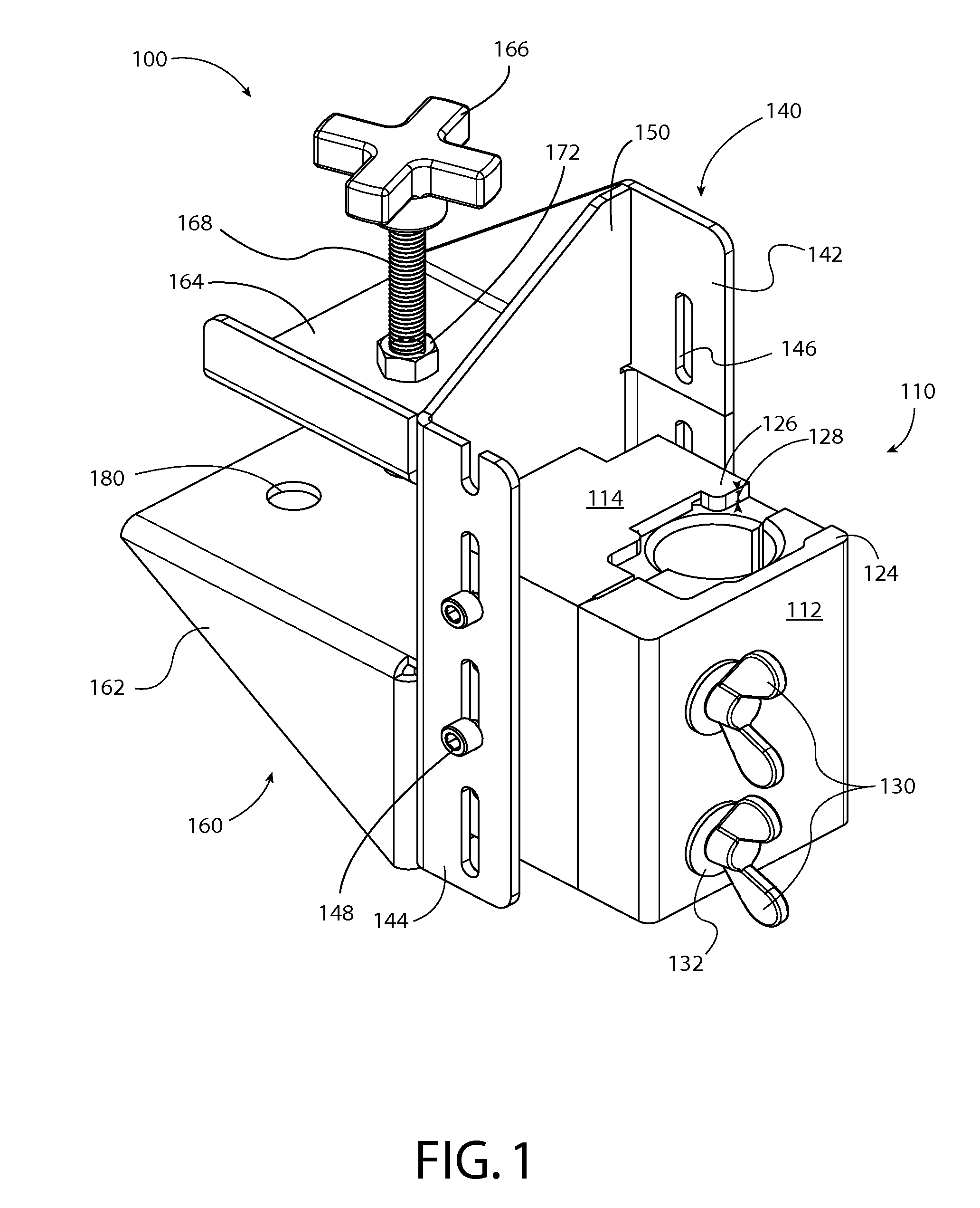
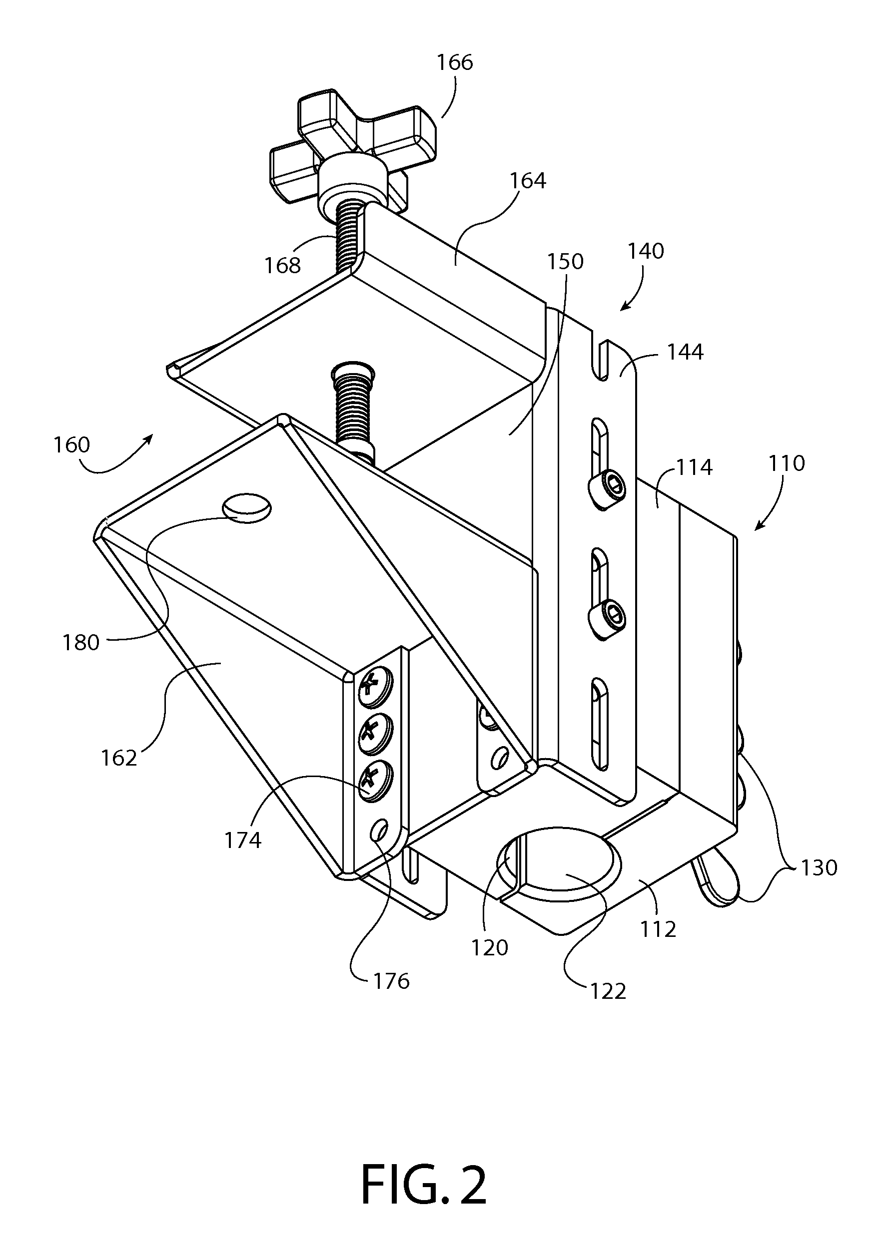
[0017]The innovation disclosed generally pertains to a mount or clamp which positively secures an orbital welder to a table, stand, or other structure such that a work piece can be precisely maneuvered through or about the welder. To ensure a secure, stable fit and accurate alignment of the welder, the clamp is configured to specifically retain a matched portion of the welder, and includes a key pattern permitting a key of the welder to mate with a key recess of the clamp. The work piece can be used in conjunction with a fixture and / or jig, or other components for alignment and retention, to properly feed the work piece to or through the clamped orbital welder.

[0018]As used herein, a key pattern is a nonlinear, two- or three-dimensional pattern that provides positive locking between a key (and components attached thereto) and a key recess (and components attached thereto). In the illustrated embodiments, a faceplate connecting an extension (e.g., handle, motor case, other extremity ...


PUM

PropertyMeasurementUnit
depthaaaaaaaaaa
structureaaaaaaaaaa
thicknessaaaaaaaaaa

Abstract

The invention described herein generally pertains to systems and methods for accurately and precisely mounting an orbital welder for static use. Clamp systems as described herein can include a keyed welding clamp assembly for retaining the orbital welder having an orbital welder clamp, a clamp adapter, and a clamp mount. Similarly, methods herein can include disposing a welder extension in a first extension recess of a first clamp portion and a second extension recess of a second clamp portion, aligning an alignment key with a first key recess of the first clamp portion and a second key recess of the second clamp portion, and closing the first clamp portion toward the second clamp portion using a clamp mechanism. An operational welding system including clamps herein can further include the orbital welder and/or components thereof.

Description

CROSS-REFERENCE TO RELATED APPLICATIONS AND INCORPORATION BY REFERENCE[0001]This U.S. patent application is a continuation of and claims the benefit of U.S. provisional patent application 61 / 903,262 filed on Nov. 11, 2013, which is incorporated herein by reference in its entirety.TECHNICAL FIELD[0002]In general, the present invention relates to arranging an orbital welder for static use. More particularly, the present invention relates to accurately and repeatably securing an orbital welder to a structure to permit maneuvering of a work piece about the orbital welder.BACKGROUND OF THE INVENTION[0003]In industrial applications, welding may involve raising, cladding, building up, filling, hard facing, overlaying, joining, and other welding applications. When confronted with a work piece having a curved surface, an orbital welding process may be used to rotate the welding head to apply a weld to the curved surface. The most common examples where orbital welding is used is the welding o...

Claims


Application Information

Patent Timeline
Patent Type & Authority Applications(United States)
IPC IPC(8): B23K37/02F16B2/12
CPCB23K37/0241F16B2/12B23K37/027B23K37/0276F16B2/065Y10T29/49826
Inventor MILLER, VICTOR
Owner LINCOLN GLOBAL INC
Why Eureka
Try Eureka