Compact optical tracker

a tracker and optical technology, applied in the field of optical trackers, can solve problems such as latency

Active Publication Date: 2015-05-21
ELBIT SYST LTD
View PDF1 Cites 5 Cited by
  • Summary
  • Abstract
  • Description
  • Claims
  • Application Information

AI Technical Summary

Benefits of technology

[0005]These additional, and / or other aspects and / or advantages of the present invention are set forth in the detailed description which follows.

Problems solved by technology

Tracking objects using video cameras requires both bandwidth and computational power that inevitably lead to latency issues.

Method used


Image

  • Compact optical tracker
  • Compact optical tracker
  • Compact optical tracker

Examples


Embodiment Construction

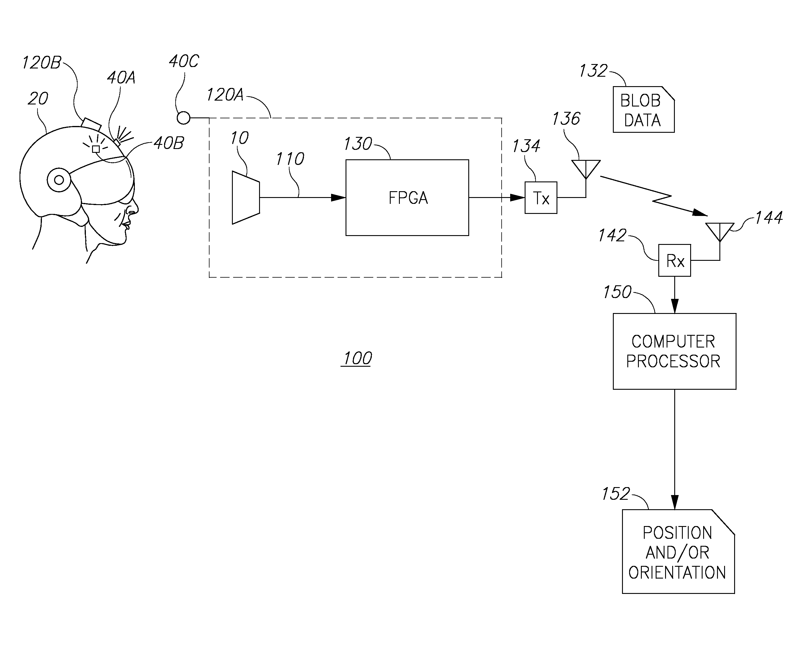
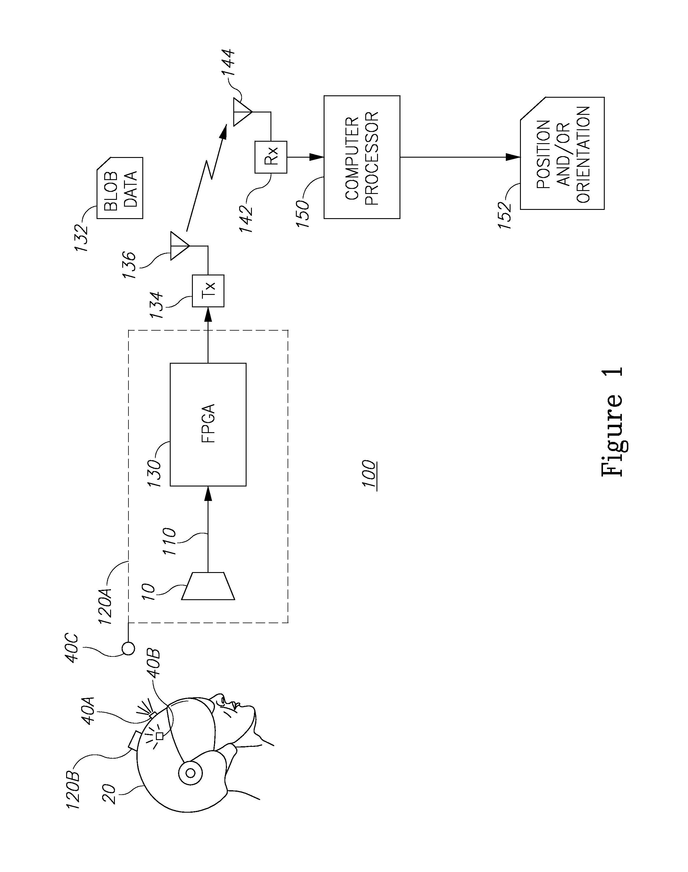
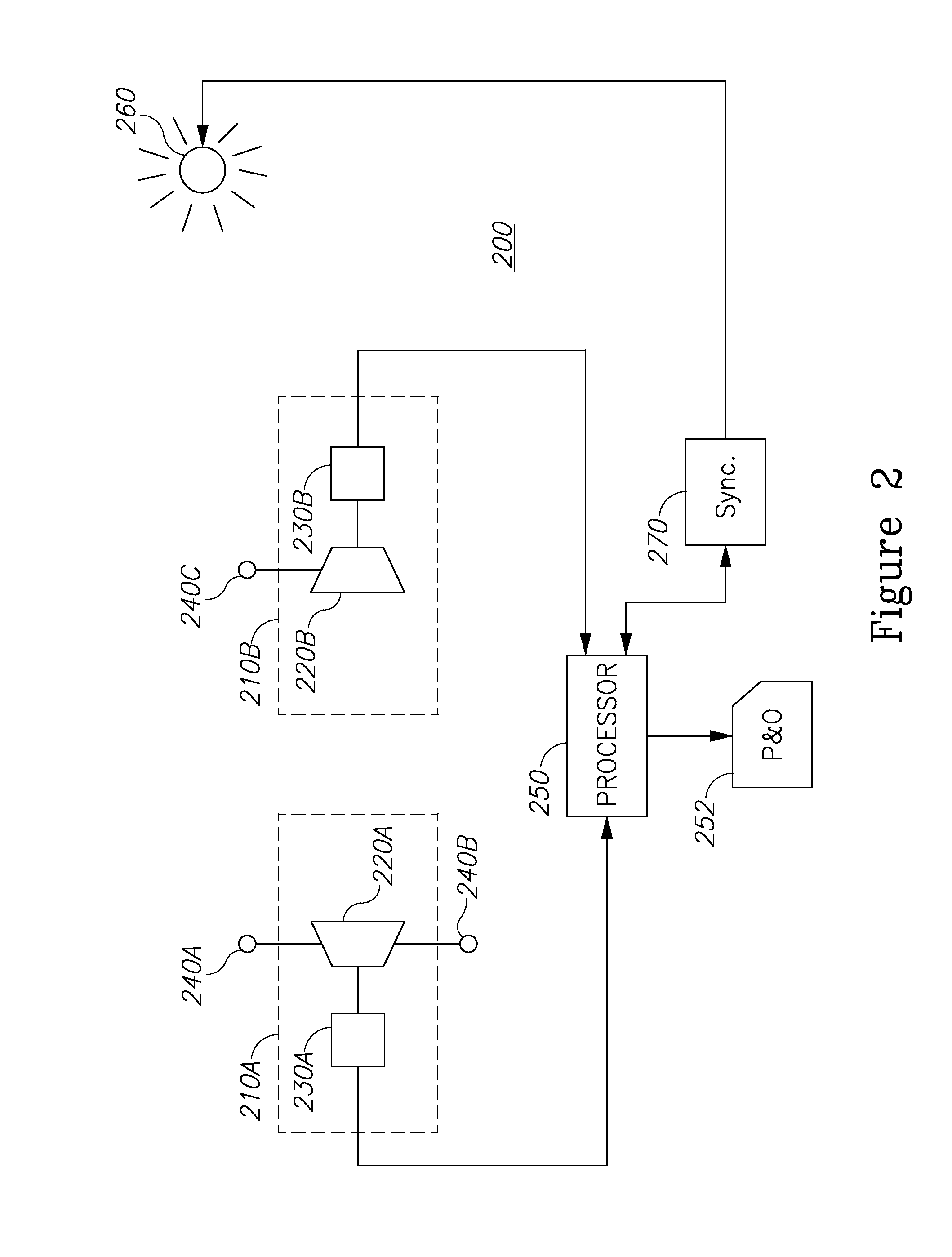
[0013]With specific reference now to the drawings in detail, it is stressed that the particulars shown are for the purpose of example and solely for discussing the preferred embodiments of the present invention, and are presented in the cause of providing what is believed to be the most useful and readily understood description of the principles and conceptual aspects of the invention. In this regard, no attempt is made to show structural details of the invention in more detail than is necessary for a fundamental understanding of the invention. The description taken with the drawings makes apparent to those skilled in the art how the several forms of the invention may be embodied in practice.

[0014]Before explaining the embodiments of the invention in detail, it is to be understood that the invention is not limited in its application to the details of construction and the arrangement of the components set forth in the following descriptions or illustrated in the drawings. The inventi...


PUM


Abstract

An optical tracker is provided herein. The tracker may include at least two optical tracker sensors, facing at least partially each other. Each optical tracker sensor may include: a pixel array sensor configured to generate a pixel-by-pixel stream of values representing a scene; at least one visual indicator physically coupled to said pixel array sensor; and an integrated circuit (IC) physically coupled to said at least one pixel array sensor, and configured to: receive said pixel-by-pixel stream of values; and apply a binary large object (BLOB) analysis to said stream, to yield BLOB parameters indicative of the at least one visual indicator present in the scene in a single pass of the pixels representing the scene; and a computer processor configured to receive said BLOB parameters and calculate a relative position and / or orientation, or a partial data thereof, of the at least two optical tracker sensors.

Description

CROSS REFERENCE TO RELATED APPLICATIONS[0001]This application claims the benefit of Israeli Patent Application No. 229563 filed on Nov. 21, 2013, which is incorporated herein by reference in its entirety.FIELD OF THE INVENTION[0002]The present invention relates generally to the field of optical trackers and more particularly, to local tracking data extraction for facilitating data transmission.BACKGROUND OF THE INVENTION[0003]Tracking objects using video cameras requires both bandwidth and computational power that inevitably lead to latency issues. In some applications it is desirable to be able to track objects quickly without the need for high computational power or a high bandwidth of the communication link between the tracking device and the control module.SUMMARY OF THE INVENTION[0004]According to some embodiments of the present invention, an optical tracker is provided herein. The tracker may include at least two optical tracker sensors, facing at least partially each other. E...

Claims


Application Information

Patent Timeline
Patent Type & Authority Applications(United States)
IPC IPC(8): G01S17/66G01S17/86G01S17/87G01S17/875
CPCG01S17/66G01S5/163A61B34/20G01S17/875A61B2034/2055G01S17/86G01S17/87
Inventor BARAK, LIORKORNBILT, RONBEN-YISHAI, RANI
Owner ELBIT SYST LTD
Why Eureka
Try Eureka