Supercharge Your Innovation With Domain-Expert AI Agents!

Cable driven joint actuator and method

a technology of actuator and actuator shaft, applied in the field of cable driven actuator and method, can solve the problems that the robot machine developed to date is limited for laboratory use, and achieve the effect of constant tension and amplify torque applied

Active Publication Date: 2015-06-04
REHABILITATION INST OF CHICAGO
View PDF5 Cites 3 Cited by
  • Summary
  • Abstract
  • Description
  • Claims
  • Application Information

AI Technical Summary

Benefits of technology

The present invention is a machine that can be used at home or outside of a laboratory for training or rehabilitating robotic or prosthetic devices for human patients. It is easy to move around and is affordable. This invention can help to make robotic training and rehabilitation more accessible for people.

Problems solved by technology

However, the robotic machines developed to date have been limited for use in a laboratory setting.

Method used


Image

  • Cable driven joint actuator and method
  • Cable driven joint actuator and method
  • Cable driven joint actuator and method

Examples


Embodiment Construction

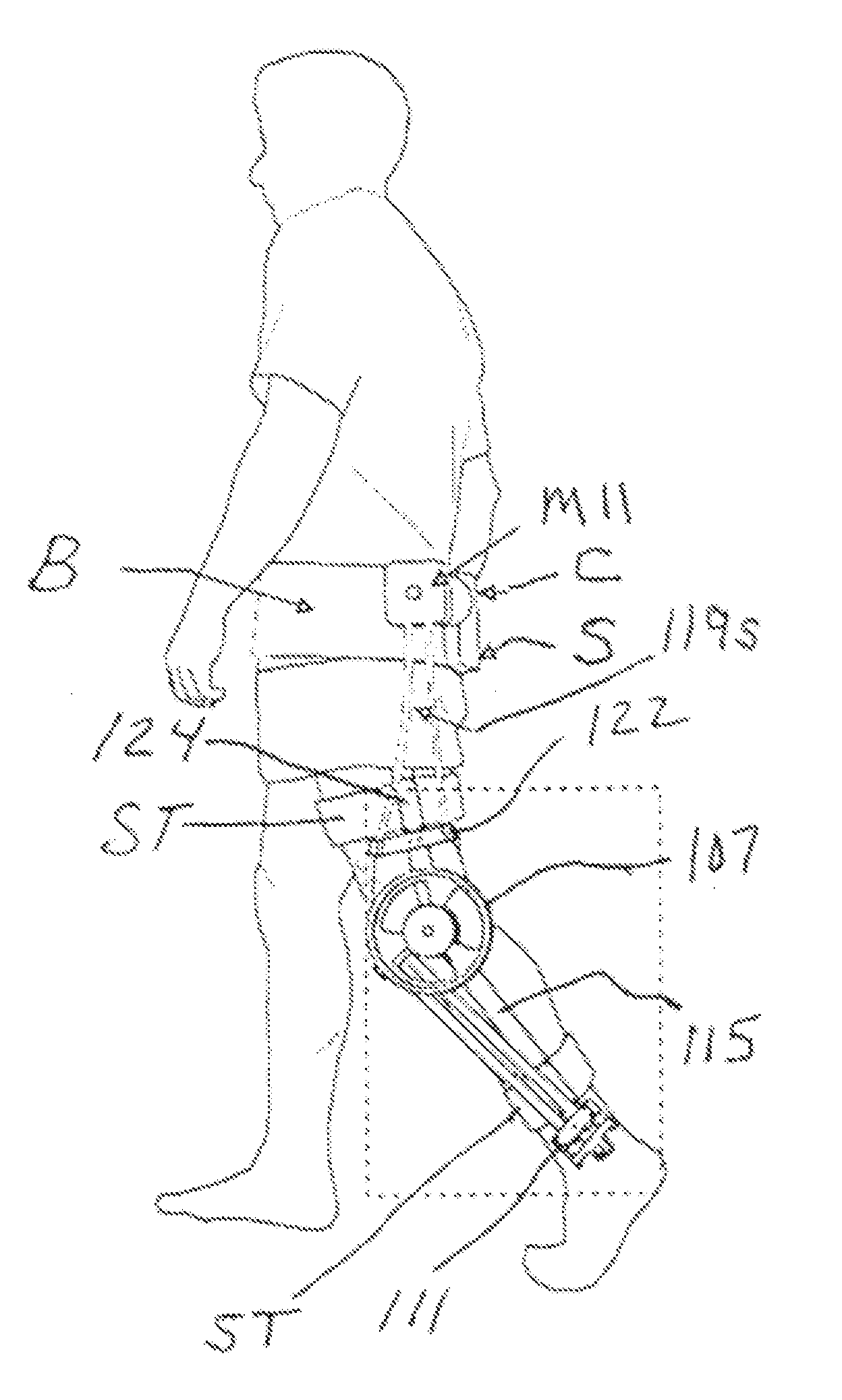
[0026]In one illustrative embodiment, the present invention provides a cable driven joint actuator mechanism that includes moment arm adjustment features to control torque applied to a joint. The joint to be actuated can include, but is not limited to, a human user's joint such as an elbow joint, a mechanical joint of a mechanical device, or any other joint.

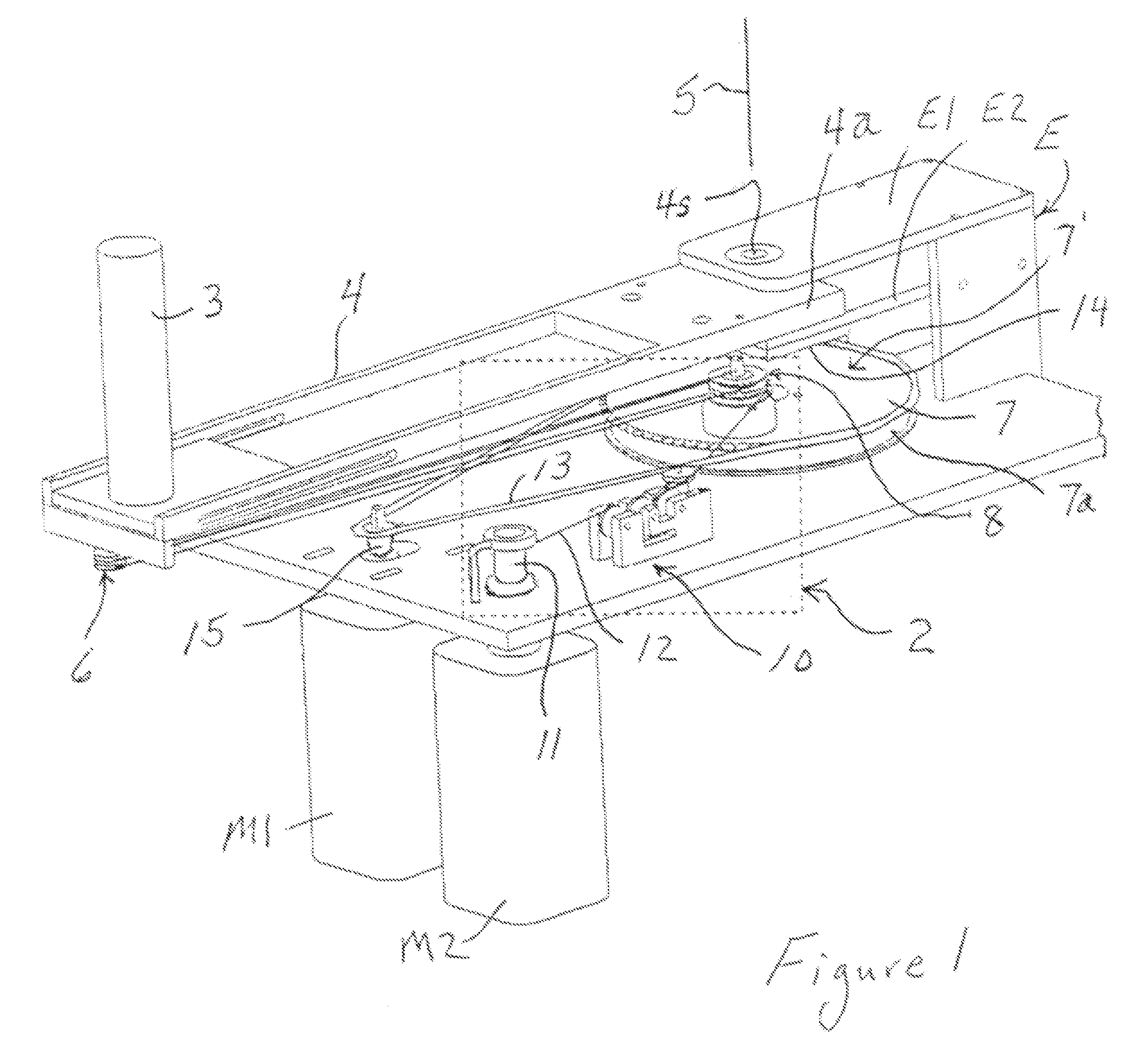
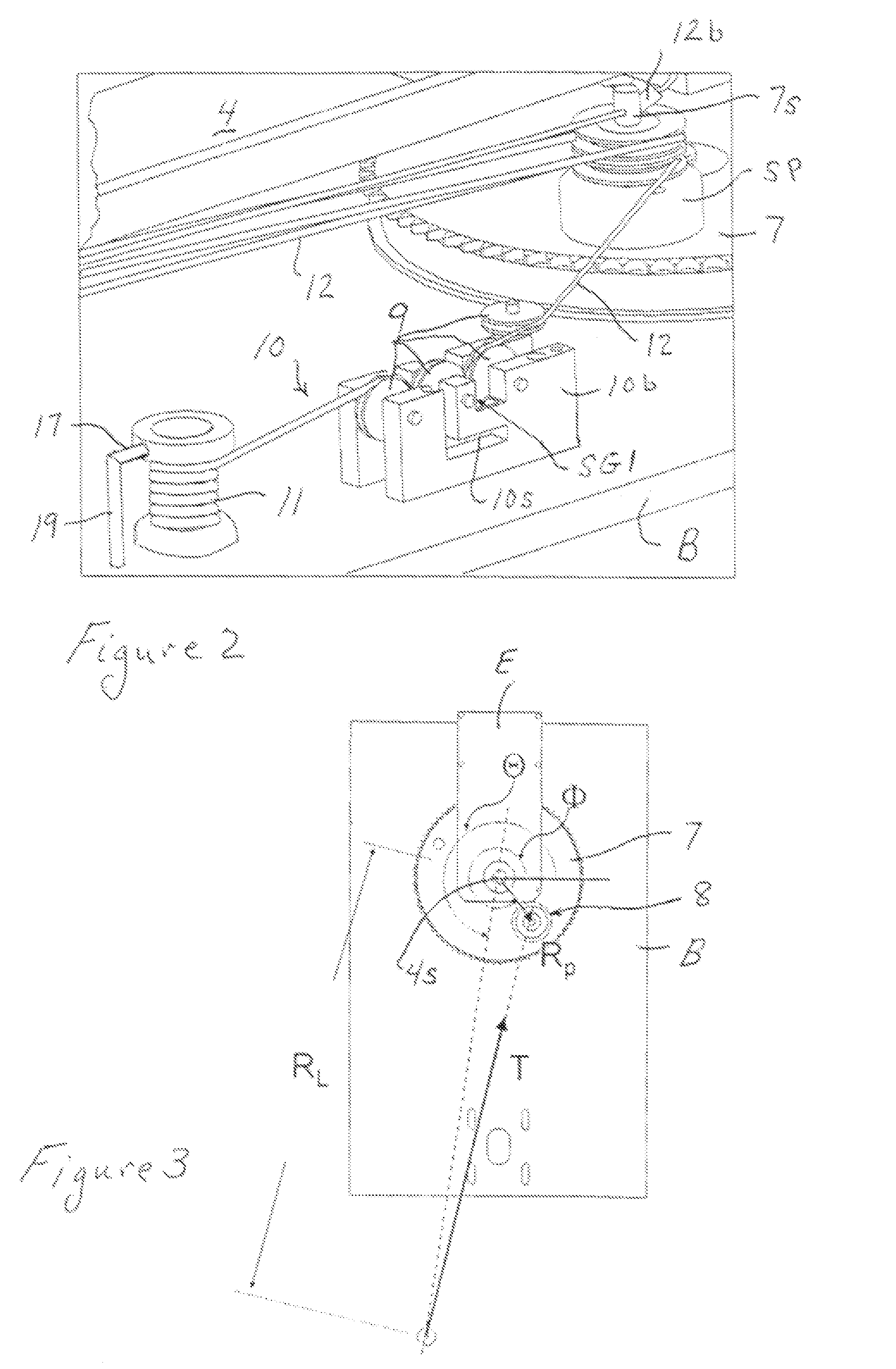
[0027]In a particular embodiment of the present invention offered for purposes of illustration and not limitation with respect to FIGS. 1 and 2, the cable driven joint actuator includes a pivotal link 4 that is adapted to be operatively coupled to a joint to be actuated and that is pivoted about a pivot axis 5 by a discrete length of substantially inelastic cable 12 engaging one or more pulleys 6 disposed on the link 4 remote from the pivot axis 5 and having a cable end coupled to the link as explained below. One or more cable positioning pulleys 8 is / are provided on a rotatable pulley-support member 7 that is rotated about a cen...


PUM


Abstract

A cable driven actuator and actuator method involve a movable link that is movable about a path by a cable connected to the link, and a movable support member having a cable routing element. The support member is movable in a manner to change a moment arm of the cable acting on the link to control torque applied to the joint.

Description

CROSS REFERENCE TO RELATED APPLICATIONS[0001]This is a divisional application that claims benefit to U.S. non-provisional application Ser. No. 11 / 809,206 filed on May 31, 2007, which claims benefit to U.S. provisional application Ser. No. 60 / 809,698 filed on May 31, 2006, which are herein incorporated by reference in their entirety.GOVERNMENT SUPPORT[0002]This invention was supported by funding from the Federal Government through the National Institute of Health Science under Grant / Contract No. 5T32 HD 07418. The Government may have certain rights in the invention.FIELD[0003]The present invention relates to a cable driven actuator and method incorporating moment arm adjustment features.BACKGROUND[0004]In rehabilitation robotic, orthotic, or prosthetic applications, devices have been used to apply forces including torques to various points on the human body in order to manipulate those points. When such devices apply forces or torques under programmable computer control, it is said t...

Claims


Application Information

Patent Timeline
Patent Type & Authority Applications(United States)
IPC IPC(8): A61F5/01F16H19/06
CPCF16H19/06A61F5/0102A61F5/0125A61H1/0237A61H1/0274A61H2201/165A63B21/0058A63B21/155A63B2220/17A63B2220/51A61H3/00A61H2201/1215A61H2201/163A61H2201/1635A61H2201/1642A61H2201/1676Y10T74/20402
Inventor PATTON, JAMES L.PESHKIN, MICHAEL A.SULZER, JAMES S.
Owner REHABILITATION INST OF CHICAGO
Features
  • R&D
  • Intellectual Property
  • Life Sciences
  • Materials
  • Tech Scout
  • Unparalleled Data Quality
  • Higher Quality Content
  • 60% Fewer Hallucinations
Learn More