

Vehicle brake device
a brake device and vehicle technology, applied in the direction of brake action initiation, brake system, transportation and packaging, etc., can solve the problems of inability to determine whether the separation piston is stuck to the housing, the seal function of the seal member cannot be damaged due to age degradation, and the inability to obtain servo pressure of an appropriate magnitud
- Summary
- Abstract
- Description
- Claims
- Application Information
AI Technical Summary
Benefits of technology
Problems solved by technology
Method used
Image

Examples
Embodiment Construction
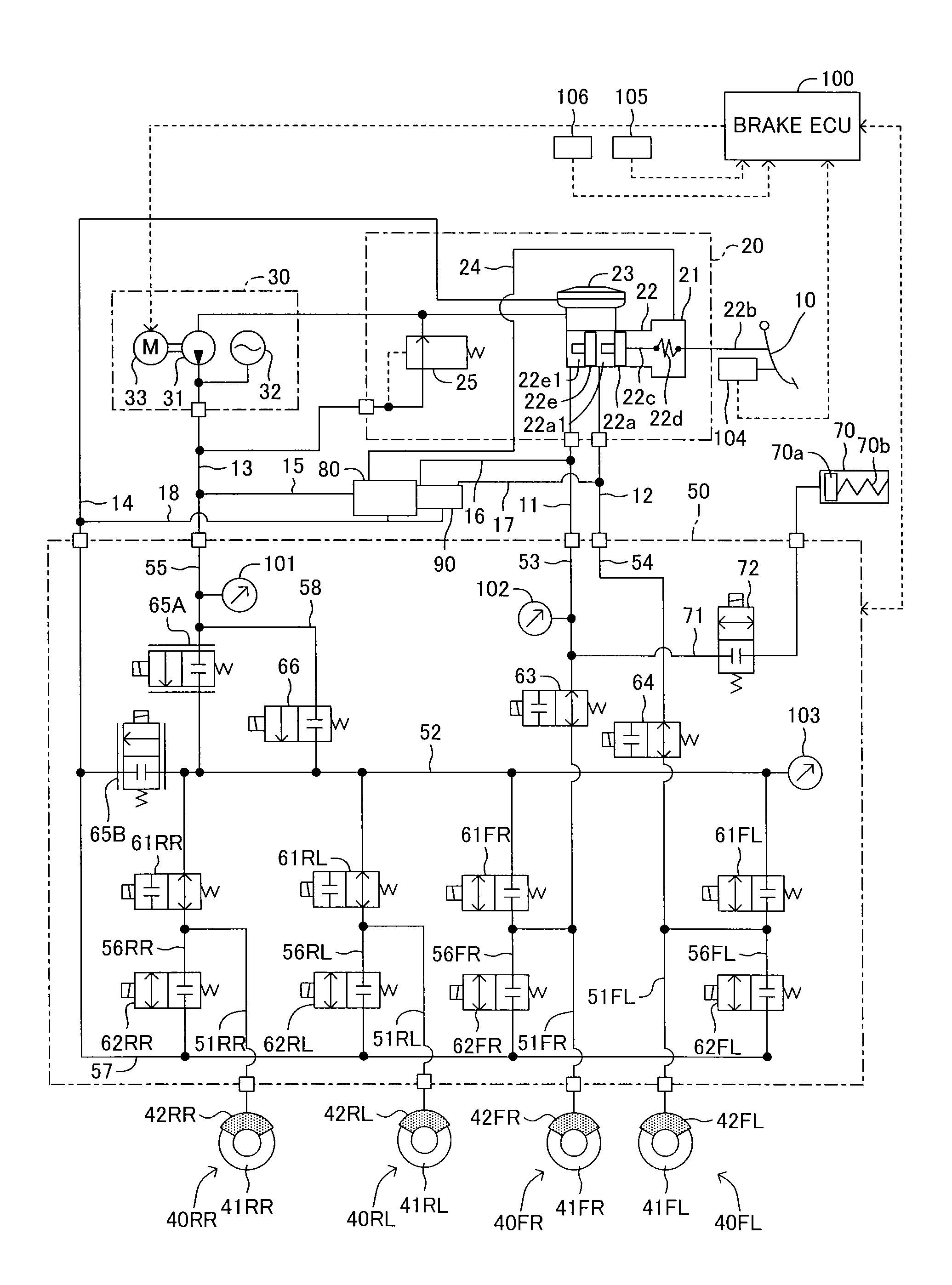
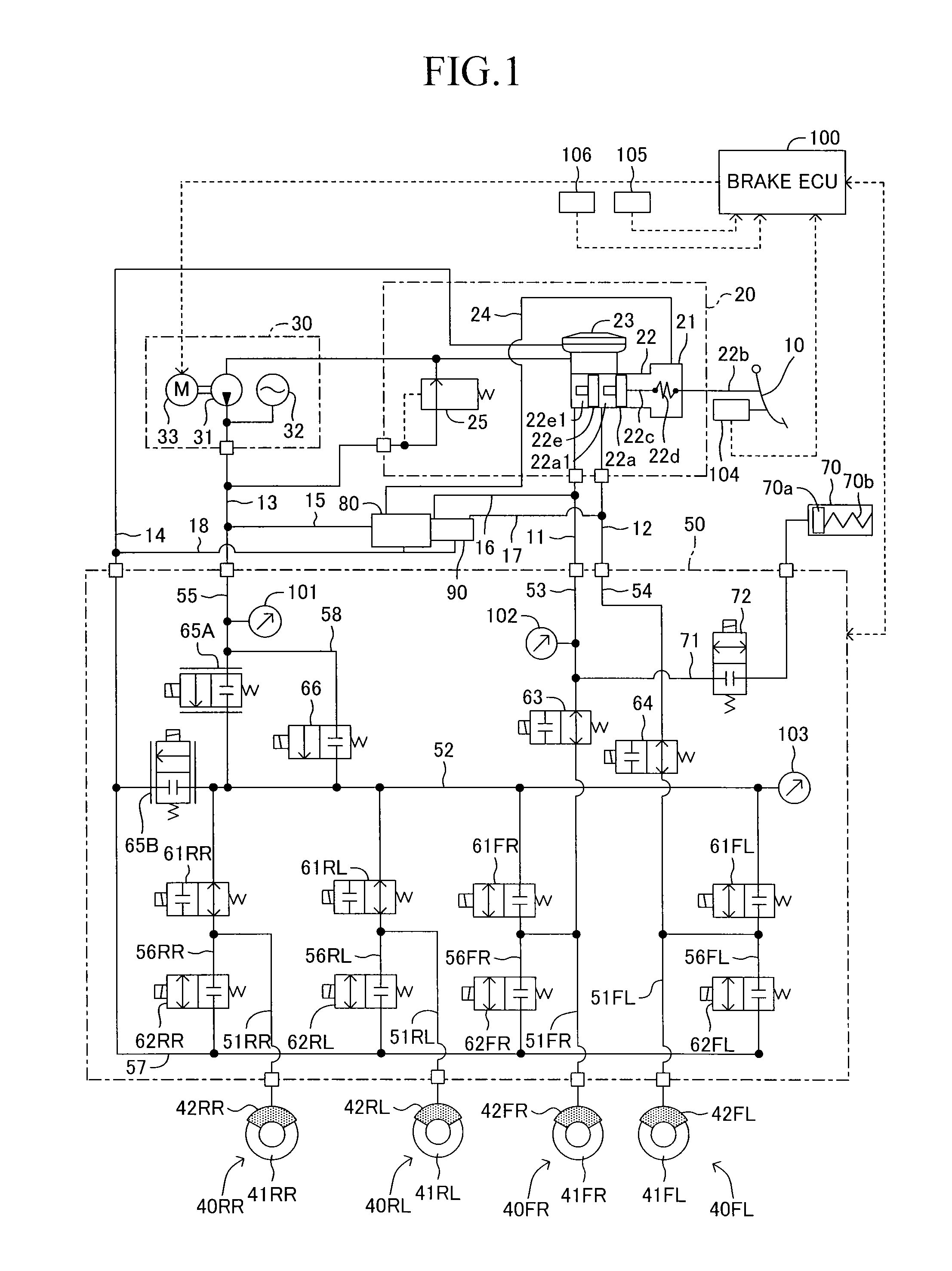
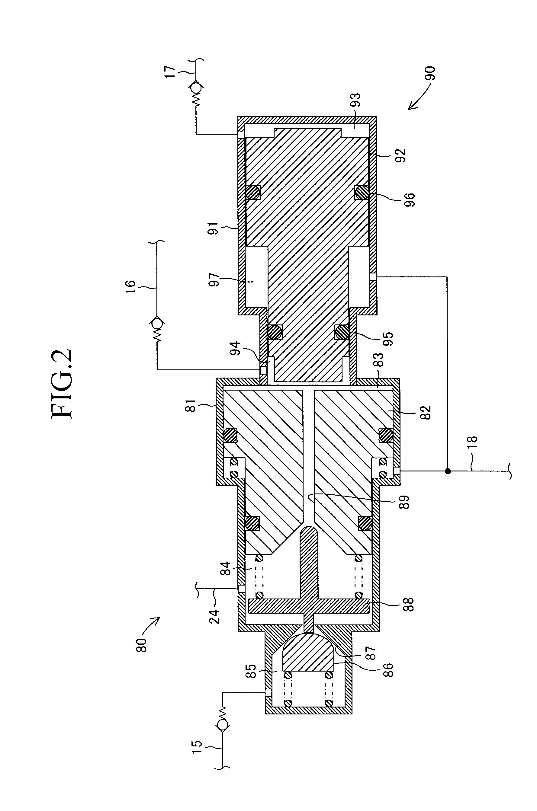
[0050]Now, a vehicle brake device according to an embodiment of the present invention is described referring to the drawings. FIG. 1 is a schematic system diagram of the vehicle brake device according to this embodiment.
[0051]The brake device according to this embodiment includes a brake pedal 10, a master cylinder unit 20, a power hydraulic pressure generation device 30, a hydraulic pressure control valve device 50, a pressure increasing mechanism 80, a separation valve mechanism 90, and a brake ECU 100 for brake control. Brake units 40FR, 40FL, 40RR, and 40RL installed on respective wheels include brake rotors 41FR, 41FL, 41RR, and 41RL, and wheel cylinders 42FR, 42FL, 42RR, and 42RL integrated into brake calipers. The brake units 40 are not limited to the case where disk brakes are installed on all the four wheels, and, for example, drum brakes may be installed on all the four wheels, or the disk brakes and the drum brakes may be arbitrarily combined in such a way that the disk b...
PUM
 Abstract
Description
Claims
Application Information