
Adjusting method and device of sensitivity of signal interpretation

a signal interpretation and sensitivity technology, applied in the direction of electric variable regulation, process and machine control, instruments, etc., can solve the problems of misjudgment to cause malfunction, deterioration of fan system b>1/b> itself cannot judge whether pulse width modulation signal, etc., to achieve the effect of reducing misjudgment and keeping heat dissipation efficiency of fan system

Active Publication Date: 2008-06-19
DELTA ELECTRONICS INC
View PDF4 Cites 9 Cited by
  • Summary
  • Abstract
  • Description
  • Claims
  • Application Information

AI Technical Summary

Benefits of technology

The invention provides an adjusting method and device for detecting abnormal signals and adjusting the sensitivity of signal interpretation. The device includes a receiving module, setting module, sampling module, judging module, or calculating module. The method involves continuously receiving an input signal, setting a sampling parameter, sampling the input signal, calculating the average of the sampling signals, judging whether the averages are the same, and generating a control signal accordingly. This allows for the detection and elimination of noise in the input signal, preventing abnormal operation of the fan system. The sensitivity of the input signal interpretation can be adjusted based on the number of times of sampling, sampling cycle, delay time, and heat dissipating efficiency of the fan system.

Problems solved by technology

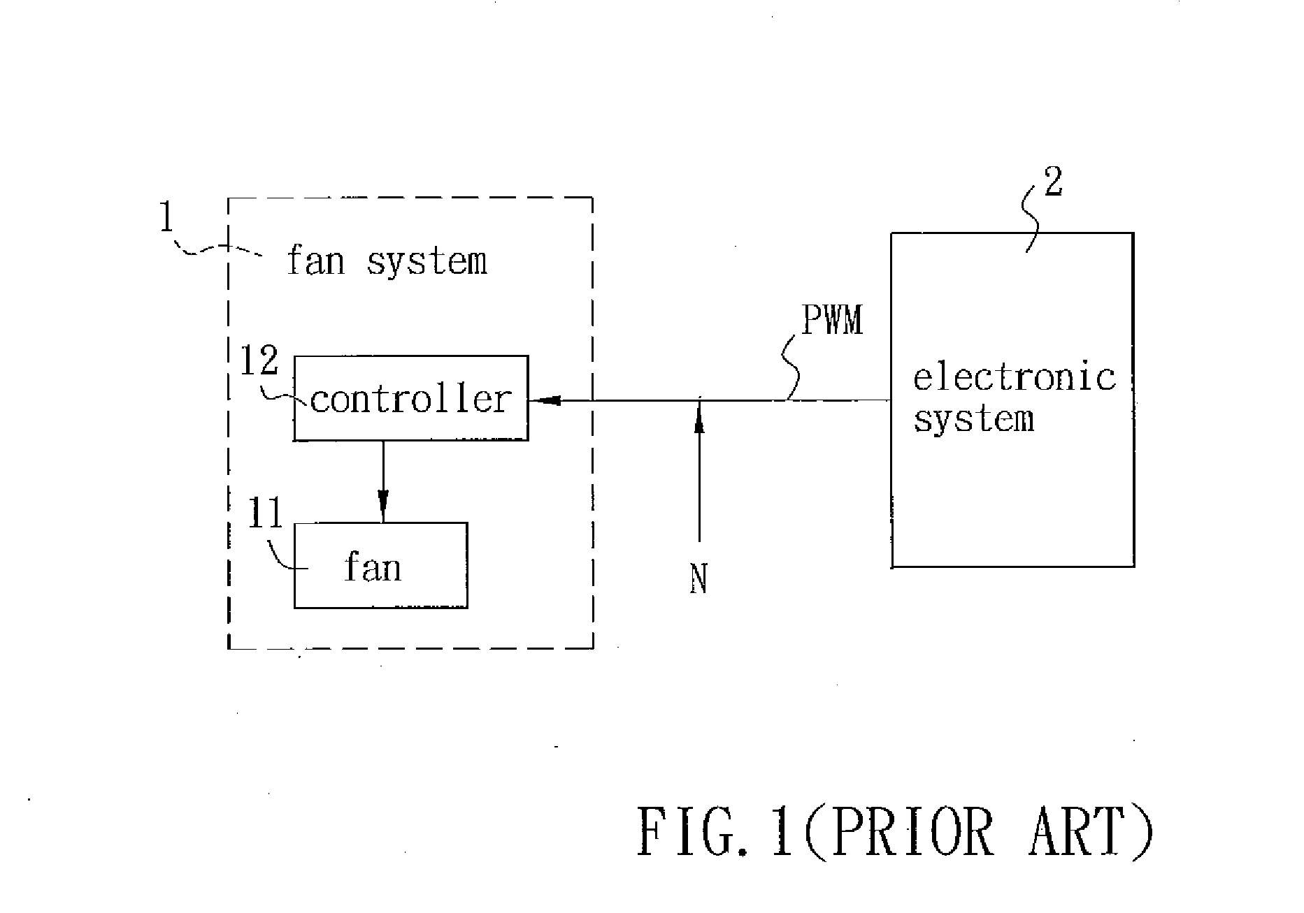
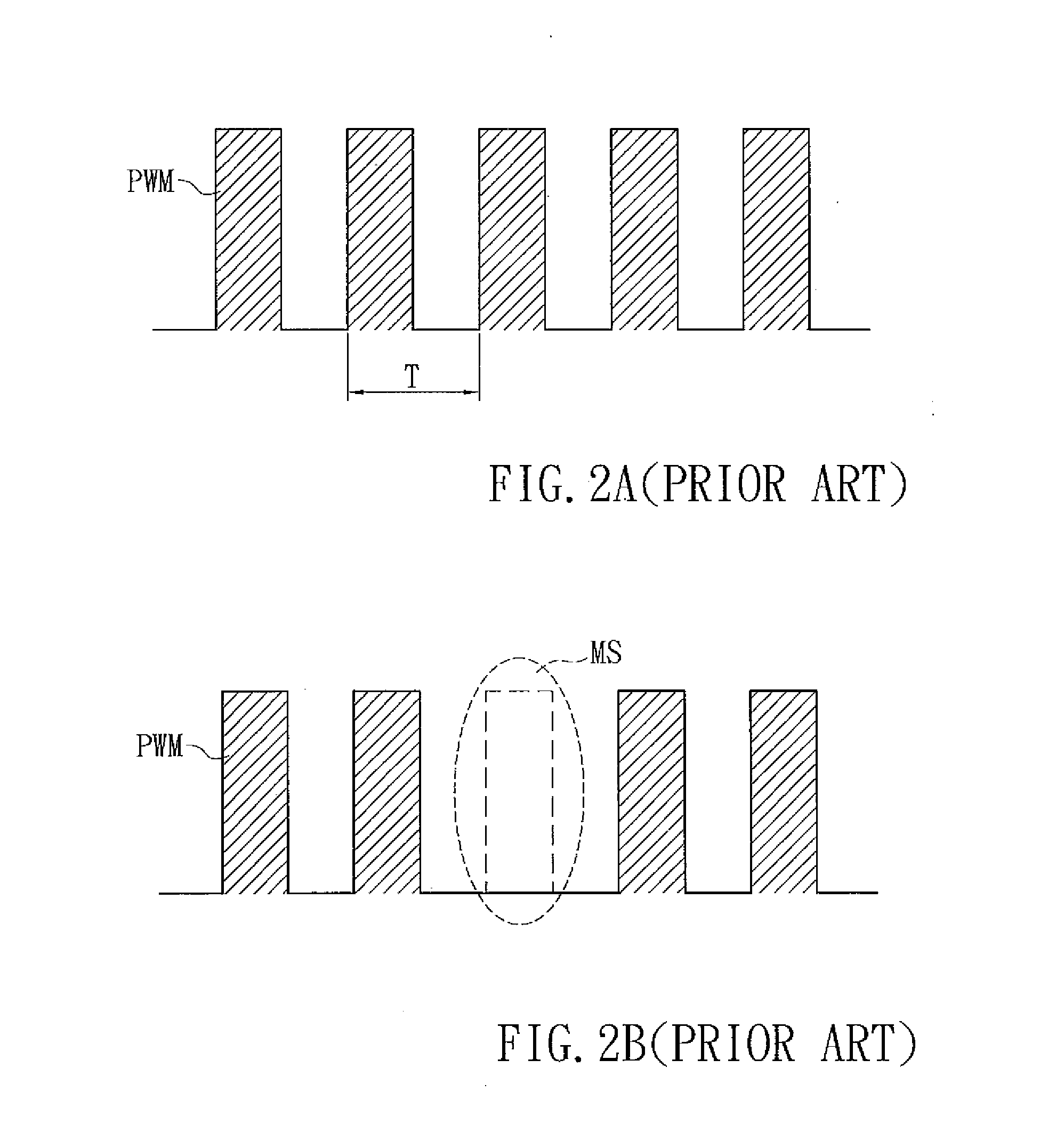
Therefore, when the fan system 1 samples the pulse width modulation signal PWM, mis-judgment may be made to cause the malfunction.
Furthermore, the fan system 1 itself cannot judge whether the pulse width modulation signal PWM has the noise N or not.
So, when this condition occurs, the rotating speed of the fan 11 is unstable, the operation of the fan system 1 is influenced, and the heat dissipating efficiency is deteriorated.

Method used


Image

  • Adjusting method and device of sensitivity of signal interpretation
  • Adjusting method and device of sensitivity of signal interpretation
  • Adjusting method and device of sensitivity of signal interpretation

Examples


Embodiment Construction

[0023]The present invention will be apparent from the following detailed description, which proceeds with reference to the accompanying drawings, wherein the same references relate to the same elements.

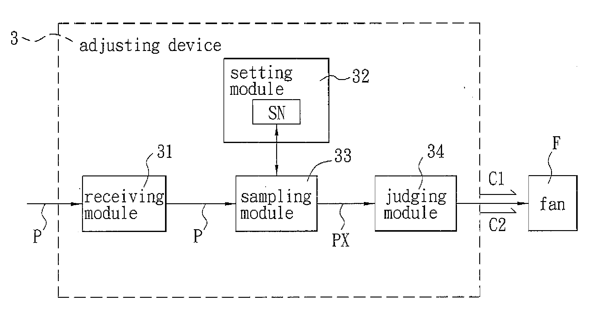
[0024]Referring to FIG. 3, an adjusting device 3 of adjusting sensitivity of signal interpretation according to a first embodiment of the invention includes a receiving module 31, a setting module 32, a sampling module 33 and a judging module 34. The application range of the adjusting device 3 is not particularly restricted and may be applied to a fan system to adjust a rotating speed of a fan F of the fan system.

[0025]The receiving module 31 is electrically connected with the sampling module 33, and continuously receives an input signal P so as to transmit the input signal P to the sampling module 33. In practice, the input signal P of this embodiment may be a pulse width modulation (PWM) signal.

[0026]The setting module 32 is electrically connected to the sampling module 33 and is fo...


PUM


Abstract

A method of adjusting sensitivity of signal interpretation includes the steps of: continuously receiving an input signal; setting a sampling parameter; sampling the input signal according to the sampling parameter to obtain a plurality of sampling signals; judging whether the sampling signals are the same or not; generating a first control signal according to the sampling signals if the sampling signals are the same; and generating a second control signal according to the input signal if the sampling signals are not the same. A device of adjusting the sensitivity of signal interpretation is also disclosed.

Description

CROSS REFERENCE TO RELATED APPLICATIONS[0001]This Non-provisional application claims priority under 35 U.S.C. §119(a) on Patent Application No(s). 095147371 filed in Taiwan, Republic of China on Dec. 18, 2006, the entire contents of which are hereby incorporated by reference.BACKGROUND OF THE INVENTION[0002]1. Field of Invention[0003]The invention relates to an adjusting method and an adjusting device, in particular, to an adjusting method and an adjusting device of adjusting sensitivity of signal interpretation in the field of fan control.[0004]2. Related Art[0005]A conventional fan system is typically driven by an electronic system, wherein the fan system has a controller or a control chip, and the controller or the control chip generates a control signal to control a rotating speed of a fan according to a change of a duty cycle of a pulse width modulation (PWM) signal, which is continuously inputted by the electronic system.[0006]Referring to FIG. 1, a conventional fan system 1 e...

Claims


Application Information

Patent Timeline
Patent Type & Authority Applications(United States)
IPC IPC(8): G05F5/00H02P7/29H02P29/00
CPCF04D27/004F04D27/00Y02B30/70
Inventor TANG, ZONG-HONGCHIU, CHIN-FAKUO, PO-TSUNCHIU, CHUN-LUNG
Owner DELTA ELECTRONICS INC
Learn More