Method Of Operating A Single-Phase Generator In Parallel With An Inverter

a single-phase generator and inverter technology, applied in the direction of emergency power supply arrangement, process and machine control, instruments, etc., can solve the problems of generator frequency fluctuation, generator frequency fluctuation,

Active Publication Date: 2015-06-25
GENERAC POWER SYSTEMS
View PDF21 Cites 21 Cited by
  • Summary
  • Abstract
  • Description
  • Claims
  • Application Information

AI Technical Summary

Benefits of technology

[0007]It is a further object and feature of the present invention to provide a system and method which permits the inverter to run independently of the single-phase generator in a first mode and in parallel with the single-phase generator in a second mode.

Problems solved by technology

However, the pulsating torque produced by a single-phase generator may result in some fluctuation in frequency of the power output by the generator.
Variations in the load applied to the generator may also cause fluctuation in the frequency of the power output by the generator.

Method used


Image

  • Method Of Operating A Single-Phase Generator In Parallel With An Inverter
  • Method Of Operating A Single-Phase Generator In Parallel With An Inverter
  • Method Of Operating A Single-Phase Generator In Parallel With An Inverter

Examples


Embodiment Construction

[0018]The various features and advantageous details of the subject matter disclosed herein are explained more fully with reference to the non-limiting embodiments described in detail in the following description.

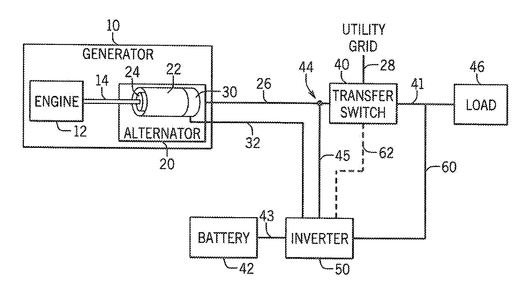
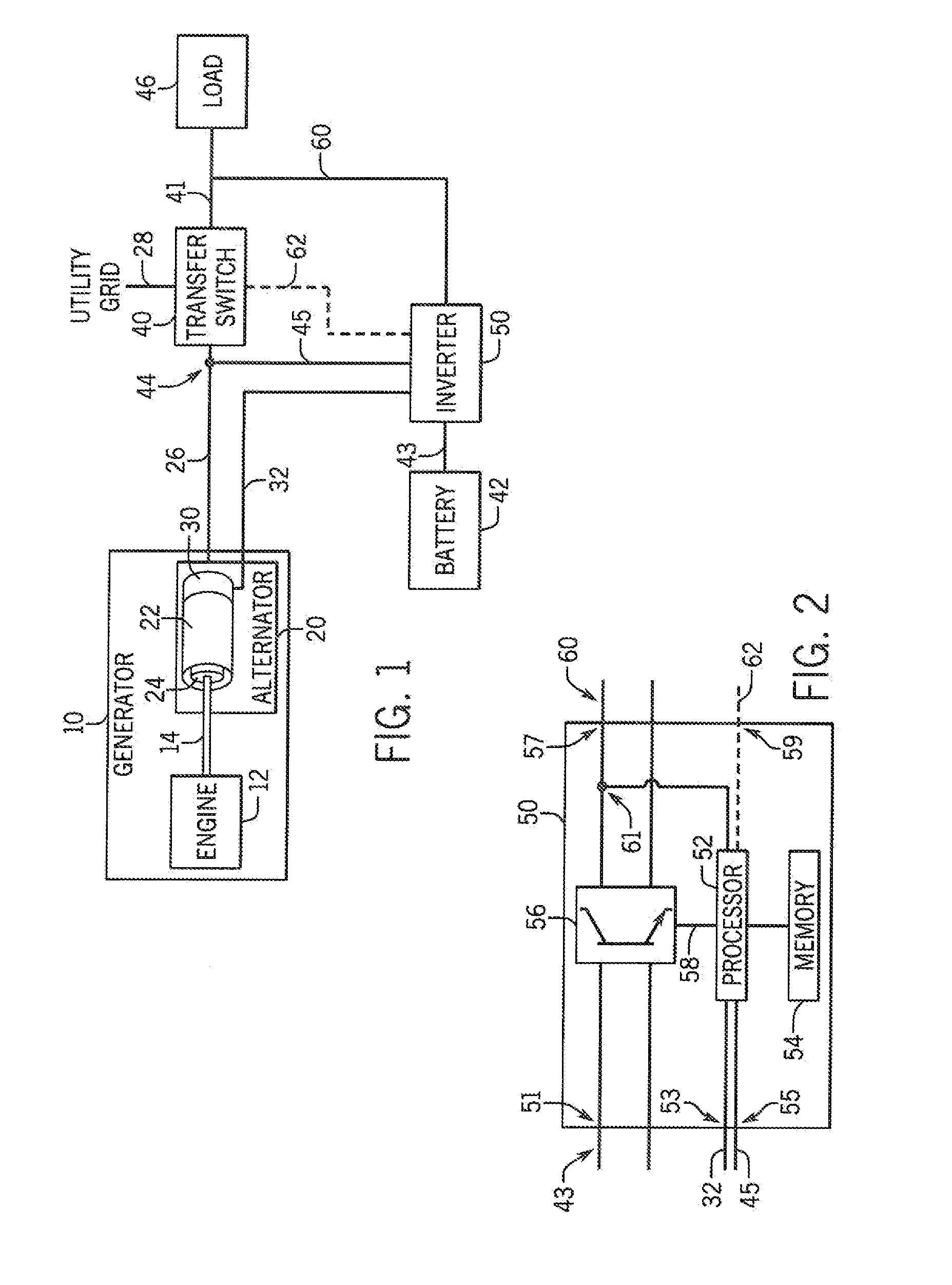
[0019]Referring to FIG. 1, an engine-driven, electrical generator system is generally represented by the reference numeral 10. The generator system 10 includes an alternator 20 defined by a cylindrical rotor 24 rotatably received within the stator 22. It is contemplated that the rotor 24 may include either permanent magnets or a winding configured to establish a magnetic field rotating with the rotor 24. The stator 22 includes a winding in which a single-phase voltage is induced responsive to the rotation of the magnetic field from the rotor 24. As a result, an AC voltage 26 is present at the output of the generator system 10. An angular position sensor 30, such as a resolver or an encoder, may be mounted to the alternator 20 and generate a measured position signal 32 corres...


PUM


Abstract

A system for connecting a single-phase generator in parallel with an inverter is disclosed. A signal corresponding to the angular position of the rotor in the generator is provided to the inverter, for example, from an angular position sensor connected to the rotor in the generator. Because variations in the load applied to the generator cause variations in the frequency of the power output by the generator, the inverter synchronizes the phase angle of the voltage output by the inverter to the angular position of the rotor.

Description

FIELD OF THE INVENTION[0001]This invention relates generally to engine-driven, electrical generators, and in particular, to a method for operating a single-phase generator in parallel with an inverter.BACKGROUND AND SUMMARY OF THE INVENTION[0002]Electrical generators are used in a wide variety of applications. Typically, an individual electrical generator operates in a stand-by mode wherein the electrical power provided by a utility grid is monitored such that, it the commercial electrical power from the utility grid fails, the engine of the electrical generator is automatically started causing the alternator to generate electrical power. When the electrical power generated by the alternator reaches a predetermined voltage and frequency desired by the customer, a transfer switch transfers the load imposed by the customer from the commercial power lines to the electrical generator. As is known, most residential electric equipment in the United States is designed to be used in connect...

Claims


Application Information

Patent Timeline
Patent Type & Authority Applications(United States)
IPC IPC(8): H02M7/493B60L50/10
CPCH02M7/493H02P9/009H02P25/04H02J3/32H02J3/08H02J9/066Y02T10/7072Y02T10/70Y02T90/14B60L53/22B60L50/10Y02T10/64Y02T10/92Y04S10/126Y02E60/00Y02T90/12H02J9/00
Inventor TESCH, TOD R.
Owner GENERAC POWER SYSTEMS
Why Eureka
Try Eureka