
Knife and sheath assembly with realeasable knife securing function

a technology of locking function and sheath assembly, which is applied in the field of locking knife and sheath assembly with releasable knife locking function, can solve the problems of commercial knife and sheath assembly that are not satisfactory in function and do not allow the knife to be removed from the sheath conveniently, so as to prevent the knife from falling out of the sheath and facilitate the removal of the knife from the sheath

Inactive Publication Date: 2015-07-09
THOMAS CRAWFORD +2
View PDF13 Cites 13 Cited by
  • Summary
  • Abstract
  • Description
  • Claims
  • Application Information

AI Technical Summary

Benefits of technology

The invention is a knife and sheath assembly with a releasable knife securing function. The purpose of this invention is to keep the knife in place and prevent it from falling out of the sheath. The assembly is also equipped with an operating member that can release the knife from the sheath for easy removal.

Problems solved by technology

Commercial knife and sheath assemblies are commonly not satisfactory in function.
Some other knife and sheath assemblies have means keep the knife firmly in the sheath, however these designs do not allow removal of the knife out of the sheath conveniently.

Method used


Image

  • Knife and sheath assembly with realeasable knife securing function
  • Knife and sheath assembly with realeasable knife securing function
  • Knife and sheath assembly with realeasable knife securing function

Examples


Embodiment Construction

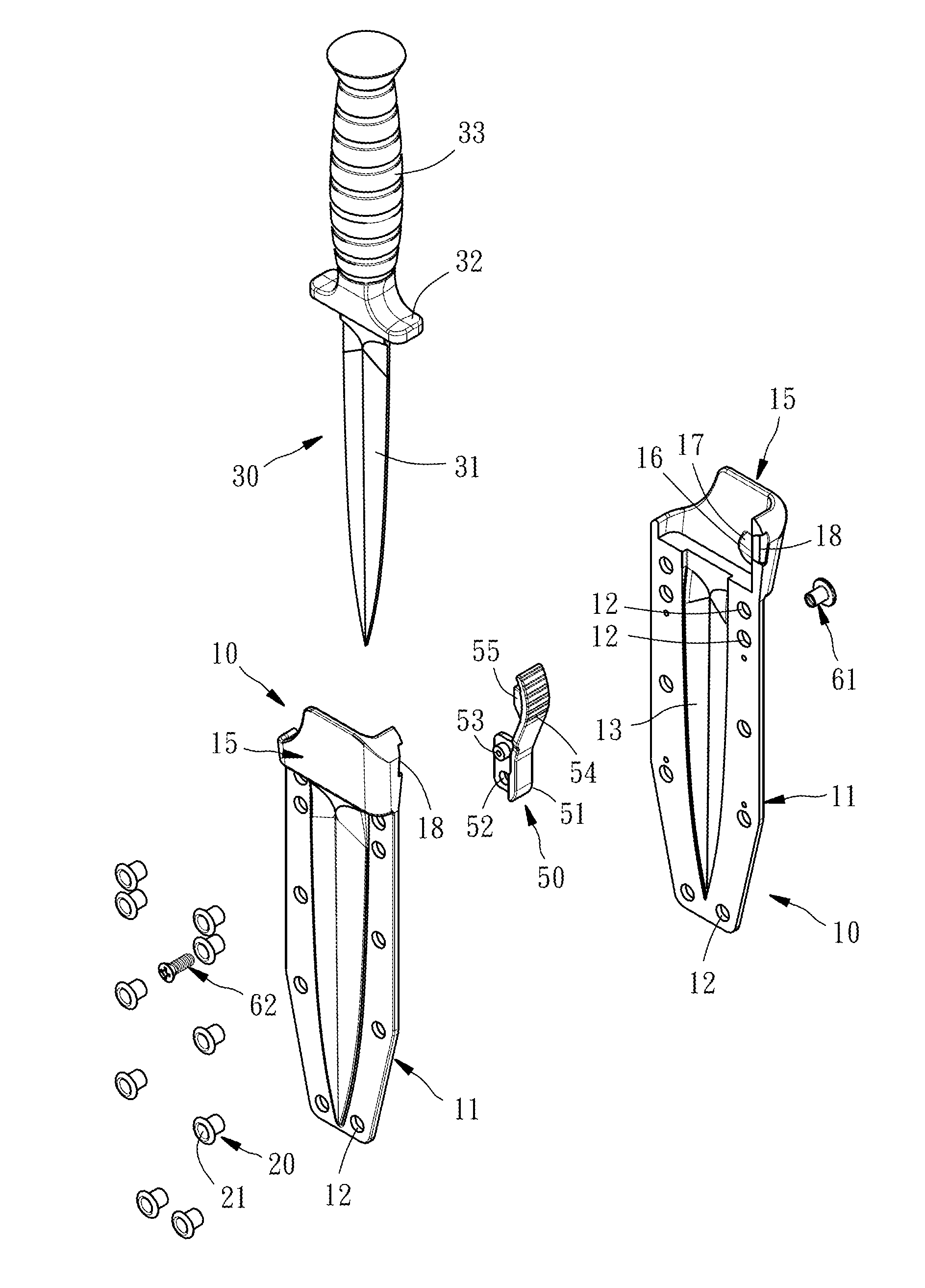
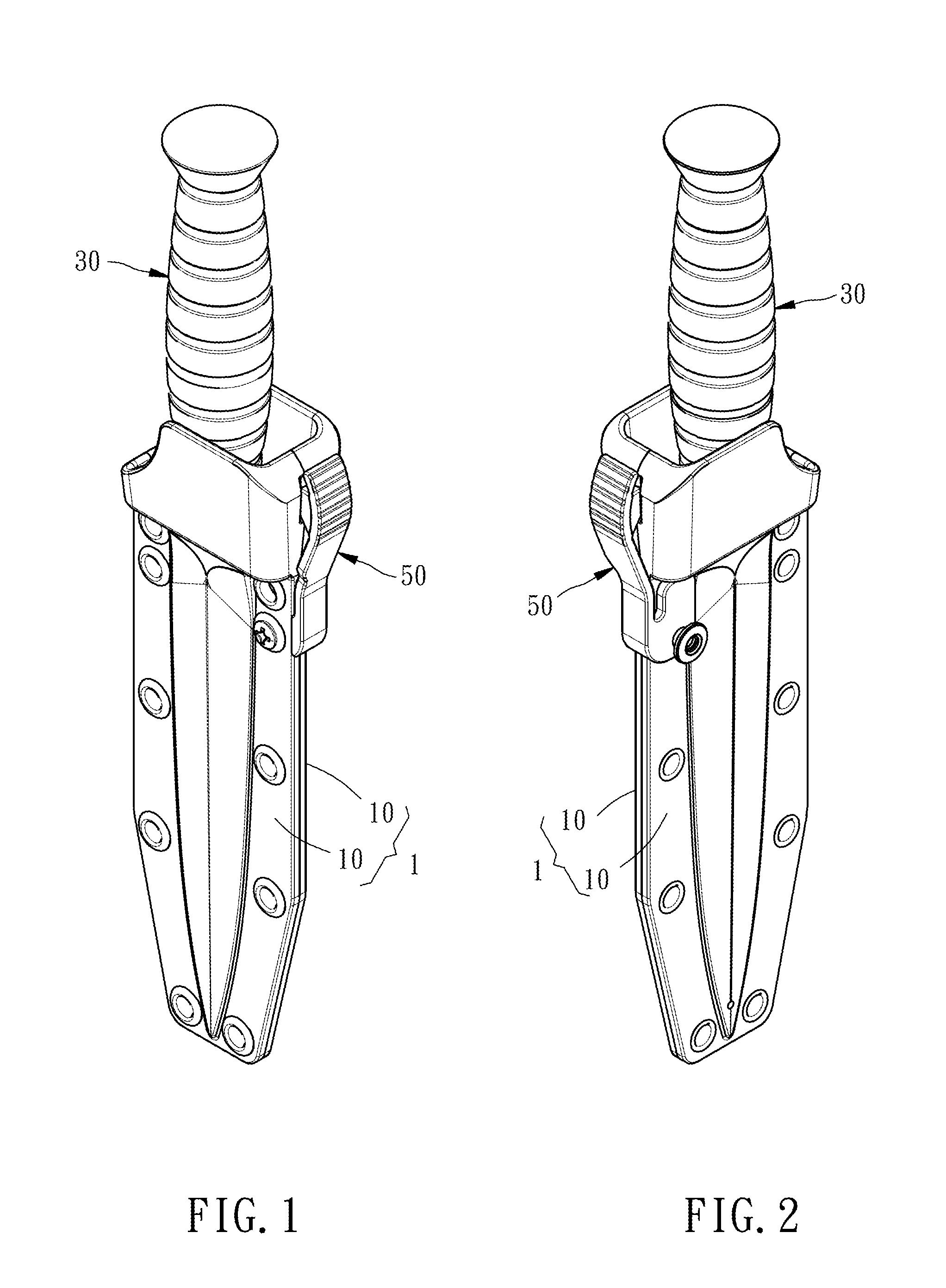
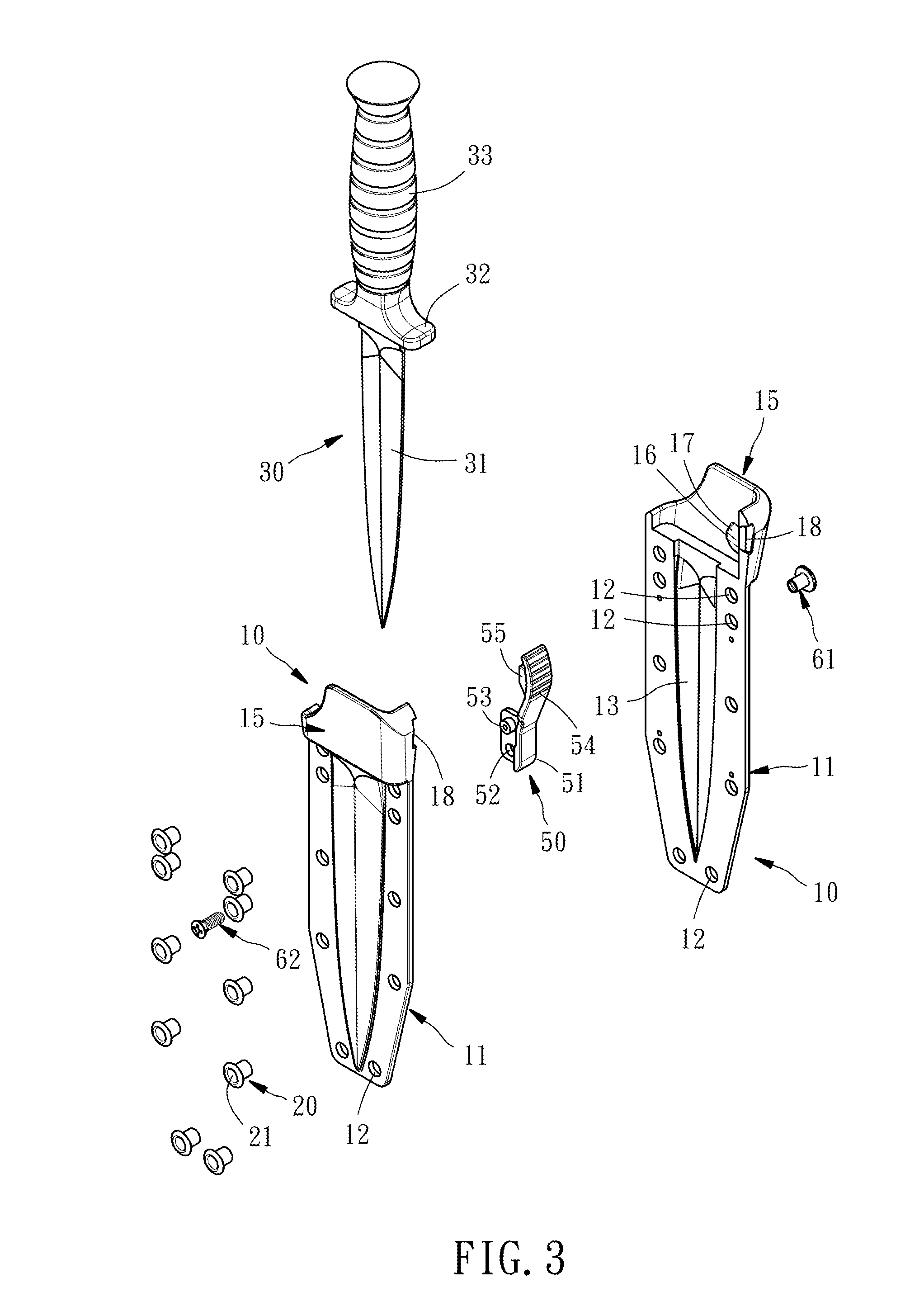
[0019]Referring to FIGS. 1-5, a knife and sheath assembly in accordance with the present invention is shown. The knife and sheath assembly comprises a sheath 1, a knife 30, and an operating member 50.

[0020]The sheath 1 is formed of two symmetrical sheath halves 10. Each sheath half 10 comprises a knife receptacle 11 defining a knife-receiving open chamber 13 and a plurality of mounting holes 12, a knife stopper 16 connected to the knife receptacle 11, and a stretchable part 18 operable to move the knife stopper 16.

[0021]As stated above, the sheath 1 is formed of the aforesaid two symmetrical sheath halves 10, and therefore, the sheath 1 comprises two knife stoppers 16. Further, the stretchable part 18 of each sheath half 10 of the sheath 1 has a beveled or arched surface 19 and form a V-shaped opening therebetween. The sheath 1 further comprises an opening-like sheath collar 15 disposed reversed to the stretchable part 18 of each sheath half 10.

[0022]Further, the two sheath halves 1...


PUM


Abstract

A knife and sheath assembly includes a sheath including a knife receptacle defining knife-receiving open chamber, a knife stopper located at the knife receptacle and a stretchable part operable to move said knife stopper, a knife including a blade insertable into the knife-receiving open chamber, a handle and a shoulder connected between the blade and the handle and stoppable by the knife stopper to keep the blade in the knife-receiving open chamber, and an operating member including a mounting part affixed to the sheath or the knife and an actuating part connected to the mounting part and operable to force the stretchable part of the sheath against the knife stopper in direction away from the shoulder of the knife.

Description

BACKGROUND OF THE INVENTION [0001]1. Field of the Invention[0002]The present invention relates to knife technology and more particularly, to a lockable knife and sheath assembly with releasable knife securing function.[0003]2. Description of the Related Art[0004]Commercial knife and sheath assemblies are commonly not satisfactory in function. The sheaths of conventional knife and sheath assemblies may have no stopper means to keep the inserted knife firmly in place. Some other knife and sheath assemblies have means keep the knife firmly in the sheath, however these designs do not allow removal of the knife out of the sheath conveniently. Therefore, there is considerable room for improvement.SUMMARY OF THE INVENTION [0005]The present invention has been accomplished under the circumstances in view. It is the main object of the present invention to provide a knife and sheath assembly with releasable knife securing function, which normally keeps the knife in place and prohibits the knif...

Claims


Application Information

Patent Timeline
Patent Type & Authority Applications(United States)
IPC IPC(8): B26B29/02
CPCB26B29/025
Inventor KOMMER, RUSSELL WILFRED
Owner THOMAS CRAWFORD
Learn More