Beverage can marketing device with removable center cover

a beverage can and center cover technology, applied in the direction of caps, liquid handling, transportation and packaging, etc., can solve the problems of contamination issues on the outer surface of beverage cans and beverage can tops such as cans, and the conventional beverage can and beverage can top configuration such as the can b> suffer from a variety of deficiencies, so as to increase sales, easy to wipe and remove, and steal market share

Inactive Publication Date: 2015-07-16
CHAPIN BARRY W
View PDF8 Cites 14 Cited by
  • Summary
  • Abstract
  • Description
  • Claims
  • Application Information

AI Technical Summary

Benefits of technology

[0026]The countersink groove 130 defined by a conventional can top 120 is a recessed crevice-like area of open space defined between the inside edge 127 of the rim 122 of the can and an outer edge 135 of the upper surface 129 (i.e. the central panel 129) of the can top (the outer edge 135 of this central panel 129 also generally defines the top inside edge of the groove 130). The groove 130 dips down in elevation below the upper surface 129 of the can top at the peripheral or outer edge 135 of the upper surface 129 of the can top 120. If a can 100 is positioned upright, the groove 130 is formed by the surface of the can top between an inside of the rim 122 (on the side of the rim facing the center of the can top) and dips or extends in elevation below the top surface 129 of the can top and ends where the upper surface of the can top begins (at the edge 135). The bottom of the groove 130 is typically the lowest point in elevation on the entire can top surface. One purpose of providing this groove is to allow the can top 120 to not distort when the contents of the can are under pressure. Thus the groove 130 provides strength to the can top design and most conventional beverage cans in use today include a groove of this nature.
[0029]Embodiments disclosed herein provide methods and apparatus to reduce or inhibit the collection of debris on the outer surfaces of beverage cans and can tops, including the rim, groove area, as well as the upper can top surface. Mechanisms and techniques disclosed herein provide embodiments that reduce health risks, cleanliness and sanitary issues posed by designs of conventional beverage cans, can tops and methods of manufacture and use thereof.
[0030]Generally, embodiments disclosed herein reduce the ability of outer surfaces of a can top and body to collect, trap and / or support growth of debris or other contaminant substances. Embodiments disclosed herein thus provide “clean can” technology that reduces the ability of a can top, rim and upper can housing area to collect debris.
[0035]In other embodiments, the central cover includes visible branding content on a top side of the central cover. In another embodiment the central cover includes visible information on an underside of the central cover. In another embodiment the visible information on the underside of the central cover is a scannable code that is operable to be scanned by a computerized device for transmission along with location information of the computerized device at a time of the scan to a remote computer system. This allows tracking of the geographic physical location of where beverage cans are opened. In another embodiment an upper surface of the rim section includes a visible branding message. In yet another embodiment, the visible information on the underside of the central cover can be a coupon providing a discount, or information to allow a consumer to participate in a contest, promotion, or customer loyalty program, or a code to allow a consumer to obtain digital content, such as a free download.
[0038]In another embodiment the central cover includes a tab connecting mechanism that temporality secures to a tab on the central panel of the can top when the central panel is placed on the can top. The tab connecting mechanism causes the tab on the can top to lift upwards from the central panel of the can top to open at least a portion of the openable section of the can top upon removal of the central cover from the device. In another embodiment the rim section secures to the can top by snapping onto an outside lower edge of the rim of the can top, the outside lower edge being formed on the can top during couple seaming of the can top to a can housing of the beverage can. In another embodiment the rim section secures to the can top along an upper inner edge of the rim of the can top and does not extend over the rim of the can top. In another embodiment the rim section and central cover are secured to the can top prior to double seaming the can top to a beverage can housing. In another embodiment the rim section and central cover are thermoformed to the can top. Thermoforming can allow the central cover to melt during formation to lay flush on the central panel of the can top and conform to the shape of the tab use to open the can. In yet another embodiment, the rim section and central cover are injection molded directly to the can top (where the can top serves to form part of the mold cavity. In another embodiment, the central cover is dome shaped and defines an area underneath the central cover the covers a tab and openable section of the central panel of the beverage can top.

Problems solved by technology

Conventional beverage can and beverage can top configurations such as those described above suffer from a variety of deficiencies.
In particular, conventional beverage cans and beverage can tops such as the can 100 and can top 120 as shown in FIG. 1 are subject to contamination issues on their outer surfaces.
Exterior surfaces of conventional cans and can tops often become “dirty” or unsanitary from exposure to various environmental contaminants shortly after the canning process is complete.
Additionally, liquid consumed either directly or indirectly from conventional beverage cans may become contaminated from debris or bacteria on the can tops due to the design of conventional beverage cans and can top or lids.
In particular, after the can top and body manufacturing and / or canning process is complete, a conventional can and can top are often exposed to a variety of unsanitary environments.
Such unsanitary environments may exist during the conventional processes of can and / or can top manufacturing, filling (canning or bottling) / seaming, packaging and shipping, and while awaiting purchase by the consuming public (e.g., while sitting on supermarket shelves and / or in refrigerators or vending machines), and after purchase but before opening of a conventional can.

Method used


Image

  • Beverage can marketing device with removable center cover
  • Beverage can marketing device with removable center cover
  • Beverage can marketing device with removable center cover

Examples


Embodiment Construction

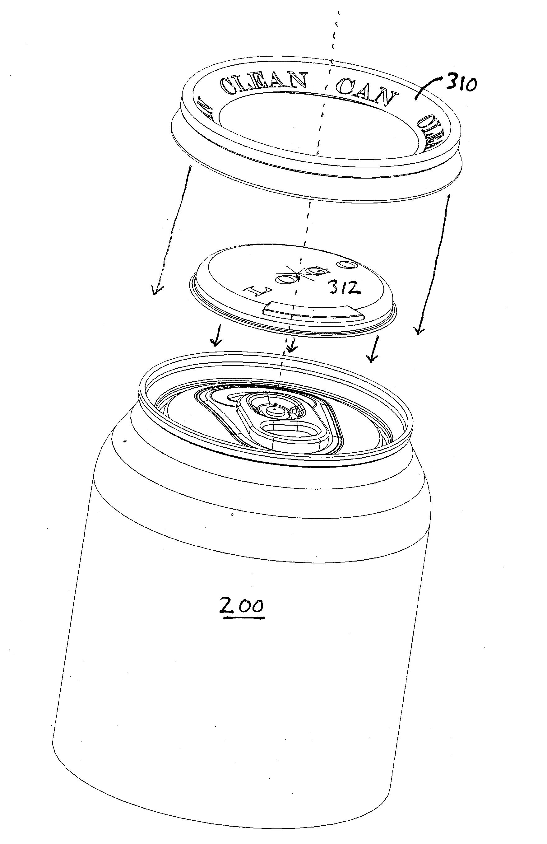
[0058]FIG. 3 shows a can top device 300 configured in accordance with one example embodiment of the present invention. FIG. 4 shows a beverage can 200 (e.g. a soda can, beer can or other beverage can) on which the can device 300 from FIG. 3 is installed.

[0059]The can top device 300 in FIGS. 3 and 4 includes a rim section 310 and a removable central cover 312. The rim section 310 is operable to be secured to the top of a beverage can 200 (as shown in FIG. 4) by snapping onto the rim of the can. The rim section 310 in this example includes an outer surface that begins at the lower edge of an outer skirt 313. The outer surface of the rim section 310 in this example extends up an outside area of the beverage can, over the rim, and slopes downwards towards the central panel of the beverage can top and over a countersink groove inside the rim of the beverage can top. The rim section 310 ends at an inner edge that joins in this example to an outer lower edge of the removable central cover ...


PUM


Abstract

A device that secures to a beverage can top includes a rim section that includes an inner edge that resides adjacent to the central panel of the can top. A central cover is secured to the can top at the inner edge of the rim section. The central cover extends over the top of a central panel of the can top and covers a tab and openable section of the can top. The central cover is removable from the rim section at a releasable boundary defined at the inner edge of the rim section. The underside of the central cover supports under-the-cover promotions that are not visible until removal of the central cover when the can is opened. When scannable codes are used, a computerized device can provide the GPS location of where the scan occurred to track GPS location of beverage can consumption by consumers and social media engagement.

Description

CLAIM TO BENEFIT OF EARLIER FILED APPLICATION[0001]This application claims the benefit of the filing date of earlier filed, co-pending, U.S. Provisional Application for Patent having Ser. No. 61 / 881,033, filed Sep. 23, 2013, entitled “Beverage Can Marketing Device With Removable Portion”, naming the same inventor as the present application. The entire disclosure, figures, photos, teachings and contents of the above-identified Patent Applications and or Issued Patents are hereby incorporated by reference in their entirety.Incorporation by Reference Filed Co-Pending Applications[0002]This application is related to the following earlier filed U.S. Applications for patent and / or issued patents, and shares common inventorship therewith:[0003]1) Provisional Application U.S. Ser. No. 61 / 254,274 filed in the U.S. Patent Office on Oct. 23, 2009 entitled “APPARATUS AND METHODS PROVIDING A CLEAN BEVERAGE CAN”, naming the same inventor as the present application.[0004]2) Provisional Application...

Claims


Application Information

Patent Timeline
Patent Type & Authority Applications(United States)
IPC IPC(8): B65D17/00B65D51/22B65D85/72B65D25/20B65D41/46
CPCB65D17/166B65D25/205B65D17/24B65D41/46B65D85/72B65D2251/0071B65D2517/0007B65D2517/0013B65D2517/0041B65D2251/0015B65D51/22B65D51/18B65D2517/0014B65D2517/0052B65D2517/0056B65D2251/0028B65D2517/0098B65D17/4012B65D17/4014B65D17/404
Inventor CHAPIN, BARRY W.
Owner CHAPIN BARRY W
Why Eureka
Try Eureka