Beverage can marketing device

a beverage can and marketing device technology, applied in the field of beverage cans and beverage can tops, can solve the problems of contamination issues on the outer surface of beverage can tops such as the can b>, conventional beverage can and beverage can top configurations such as those described above, and suffer from a variety of deficiencies

Inactive Publication Date: 2012-06-07
CHAPIN BARRY W
View PDF6 Cites 5 Cited by
  • Summary
  • Abstract
  • Description
  • Claims
  • Application Information

AI Technical Summary

Benefits of technology

[0019]The countersink groove 130 defined by a conventional can top 120 is a recessed crevice-like area of open space defined between the inside edge 127 of the rim 122 of the can and an outer edge 135 of the upper surface 129 (i.e. the central panel) of the can top (the outer edge 135 of this central panel 129 also generally defines the top inside edge of the groove 130). The groove 130 dips down in elevation below the upper surface 129 of the can top at the peripheral or outer edge 135 of the upper surface 129 of the can top 120. If a can 100 is positioned upright, the groove 130 is formed by the surface of the can top between an inside of the rim 122 (on the side of the rim facing the center of the can top) and dips or extends in elevation below the top surface 129 of the can top and ends where the upper surface of the can top begins (at the edge 135). This groove 130 is often the lowest point in elevation on the entire can top surface. One purpose of providing this groove is to allow the can top 120 to not distort when the contents of the can are under pressure. Thus the groove 130 provides strength to the can top design and most conventional beverage cans in use today include a groove of this nature.
[0021]Embodiments disclosed herein provide methods and apparatus to reduce or inhibit the collection of debris on the outer surfaces of beverage cans and can tops. Mechanisms and techniques disclosed herein provide embodiments that reduce health risks, cleanliness and sanitary issues posed by designs of conventional beverage cans, can tops and methods of manufacture and use thereof. Generally, embodiments disclosed herein reduce the ability of outer surfaces of a can top and body to collect, trap and / or support growth of debris or other contaminant substances. Embodiments disclosed herein thus provide “clean can” technology that reduces the ability of a can top and can to collect debris. In particular, several embodiments disclosed herein remove the surface presence of the groove in the can top design by providing a groove cover that covers and essentially eliminates the surface presence of the groove from the path of the liquid flowing form the opening of the can. The groove cover can be placed over the groove and provides an upper groove cover surface that enables easy wiping of the exterior surfaces of the can top. The groove covers slopes up the inside of the rim and thus provides a nice seamless (e.g. no corners to clean or trap dirt) transition to wipe dirt up and off of the rim. Some embodiments fill in the groove, while others reside totally above the groove. By filling in or covering or residing above the groove and providing a smoother and cleaner can top surface (as opposed to the presence of the groove on a conventional can top), a more health friendly can top design is disclosed. Wiping of a can top equipped with embodiments disclosed herein also promotes easier removal of contaminants that resides on the exterior can top surfaces.
[0023]In example embodiments, the groove cover fills a portion of the groove near or closest to the openable section in the can top. In other embodiments, the groove cover fills-in the entire groove defined in the can top. In other configurations, the groove cover extends from an inside edge that starts on the upper can top surface and extends upward and radially outward (from the center of the can) up towards a region near, at or above the top of the rim, thus providing a sloped surface from the center panel up towards the top of the rim. In some configurations, the device resides totally above the groove, and does not enter the groove at all. Even the underside of the device does not need to interfere with or fill in the groove. In yet other configurations, the groove cover extends up and over the rim or perimeter of the can top and covers and fills-in a rim groove defined at an intersection of an outer lower edge of the rim of the can top and the can body. This rim groove (at the lower outside edge of the rim of the can top) is susceptible to debris collection during handling of the can. In other example embodiments, the groove cover provides a substantially smooth surface allowing ease of wiping of debris from the can top, and prevents debris from collecting or getting stuck in the groove (both the groove in the can top, and for embodiments that extend the groove cover over the rim, for the rim groove) for portions (or all) of the groove filled with the groove cover.
[0025]In some configurations the groove ring remains in place during shipping, and before, during and after dispensing liquid from the openable section in the upper surface of the can top. Other configurations provide a removable groove ring that can be applied to a can, used while opening and drinking or pouring liquid from the can, and then taken off and reused on another can. In general, the configurations of the groove ring disclosed herein prevent dirt and debris from getting into the groove of the can top and provides for a cleaner and more tasteful and more sanitary and cleaner can drinking experience. The groove ring does not prevent all debris from collecting on the can top, however the groove ring greatly assists removal of dirt and debris when the can top is wiped by a person just prior to opening the can since the groove of the can top can no longer serve as a receptacle for such dirt or debris that is wiped away. During wiping, surface dirt on the can top is able to slide easily over the upper groove cover surface of the groove ring instead of going down into the groove.Can manufacturing and bottling operations must be very fast. Embodiments of the groove ring and groove cover disclosed herein are quick to apply, inexpensive to manufacture and apply, and do not significantly slow down the canning / bottling process or can top manufacturing process. The designs provide for a much more cleanly drinking experience and can be marketed as such. Modern consumers are very concerned about their health and well-being and the groove ring technology disclosed herein provides a “clean-can” drinking experience. Customers of one brand of beverage might be enticed to switch over to another beverage brand due to the clean can technology disclosed herein. Thus the present invention provides a strong marketing tool since beverage cans that employ the techniques and apparatus disclosed herein provide a competitive advantage by offering a cleaner can top from which to drink from.

Problems solved by technology

Conventional beverage can and beverage can top configurations such as those described above suffer from a variety of deficiencies.
In particular, conventional beverage cans and beverage can tops such as the can 100 and can top 120 as shown in FIG. 1 are subject to contamination issues on their outer surfaces.
Exterior surfaces of conventional cans and can tops often become “dirty” or unsanitary from exposure to various environmental contaminants shortly after the canning process is complete.
Additionally, liquid consumed either directly or indirectly from conventional beverage cans can become contaminated due to the design of conventional beverage cans and can top or lids.
In particular, after the can top and body manufacturing and / or canning process is complete, a conventional can and can top are often exposed to a variety of unsanitary environments.
Such unsanitary environments may exist during the conventional processes of can and / or can top manufacturing, filling (canning or bottling) / seaming, packaging and shipping, and while awaiting purchase by the consuming public (e.g., while sitting on supermarket shelves and / or in refrigerators or vending machines), and after purchase but before opening of the a conventional can.

Method used


Image

  • Beverage can marketing device
  • Beverage can marketing device
  • Beverage can marketing device

Examples


Embodiment Construction

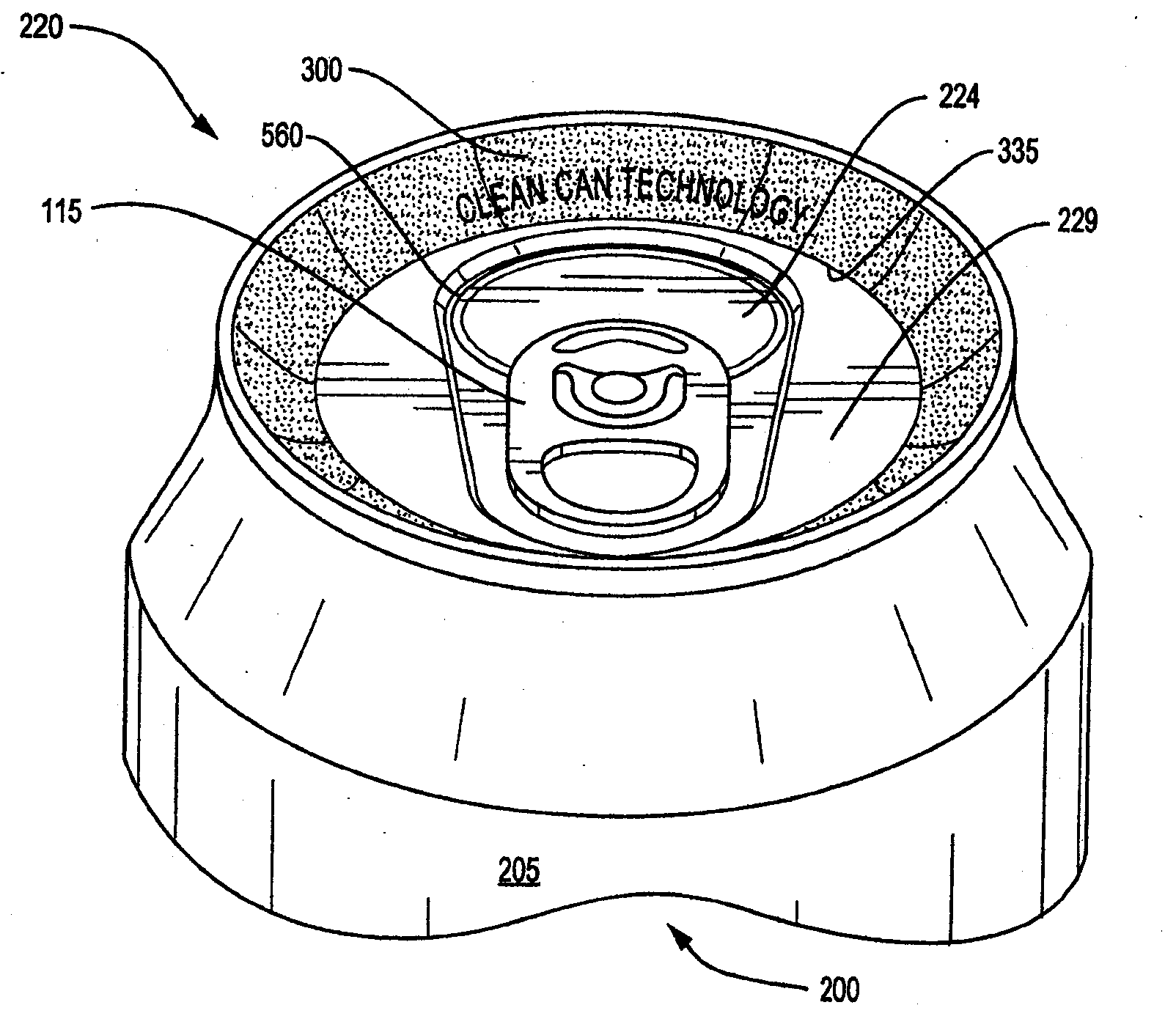
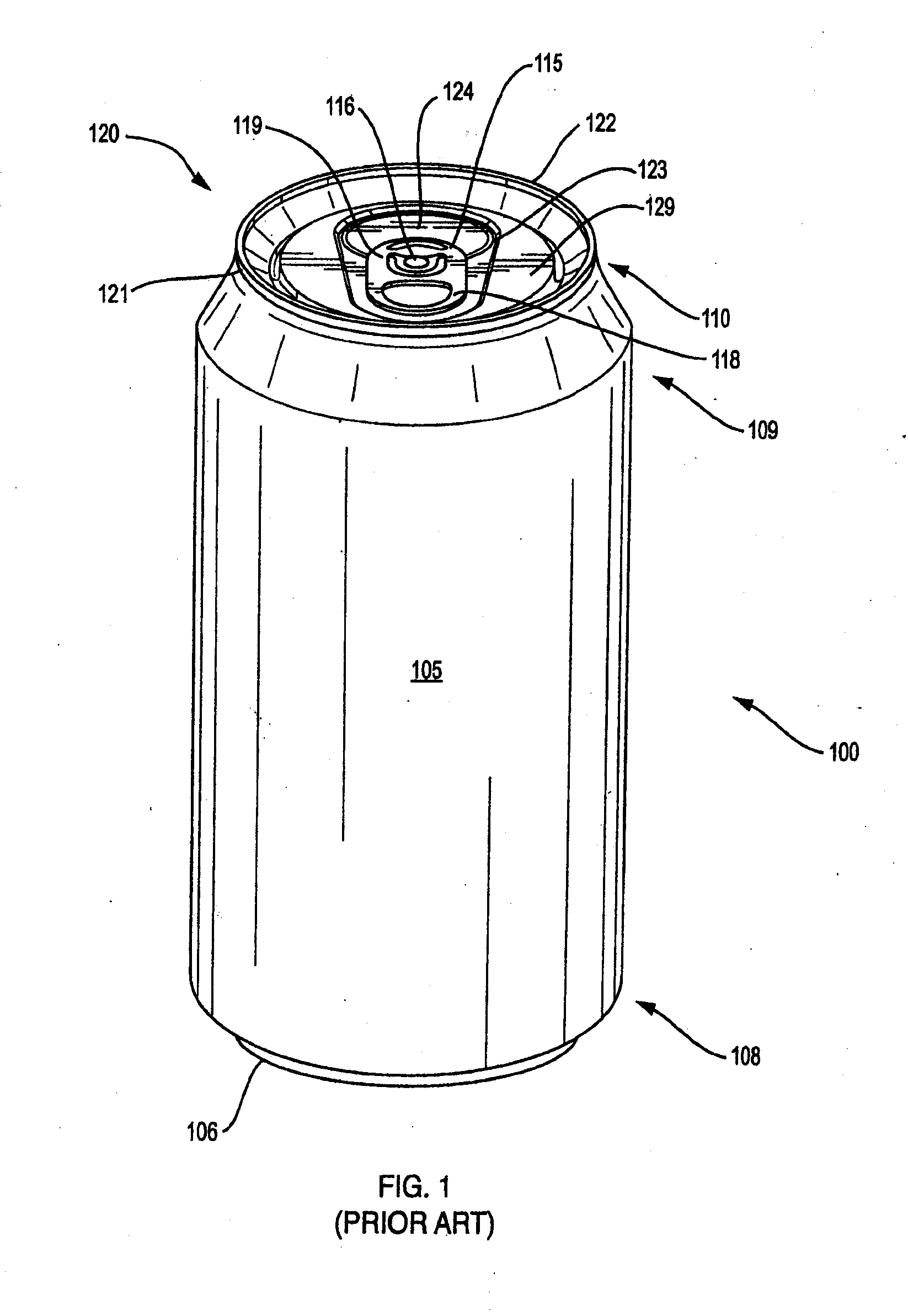
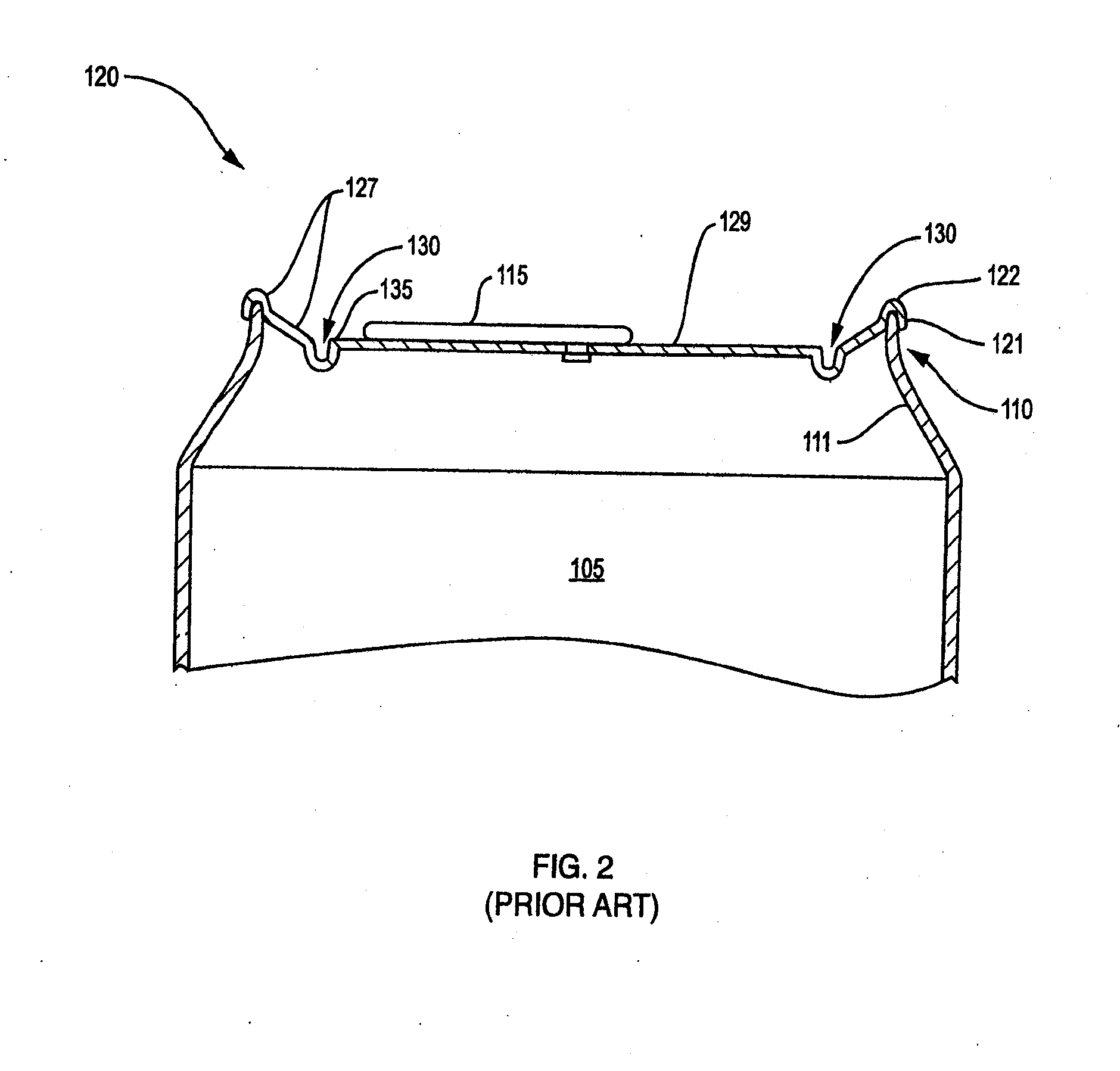
[0079]Embodiments disclosed herein provide “Clean Can” technology that provides for more sanitary beverage cans and can tops. Beverage cans have been in use for many years in packaging of many types of alcoholic and non-alcoholic beverages such as soda, pop, soft drinks, fruit juice, beer, wine and even water. A sanitary issue that is present in conventional cans and can tops is that conventional can tops define a countersink groove, crevice, or well area that surrounds an upper surface of conventional can tops, and is typically defined just along the inside of the rim of the can. The groove is provided to add strength to the can top, especially for carbonated beverages. This groove is highly susceptible to collection of unwanted dust, dirt, debris, grime, microbes or other unwanted debris. This can happen from debris that settles onto the can top and then that falls into the groove during shifting, movement or handling of the can, or may result when a person wipes a conventional ca...


PUM


Abstract

A “clean can” beverage can includes a beverage can body and a beverage can top coupled to the body. The can top is shaped to define a groove between a lower inside edge of the rim of the can top and an upper surface of the can top. A groove cover is disposed to cover the groove along at least a portion of the groove that is located adjacent to the openable section of the can top. The groove cover prevents collection of debris in the groove. The groove allows the can top to be wiped clean without debris getting stuck in the groove by sloping upwards towards the top of the rim. The groove cover can also cover the rim and an upper portion of the can body. The groove cover provides a more sanitary drinking experience and serves as a marketing surface.

Description

RELATED APPLICATIONS[0001]This application is a continuation of earlier filed U.S. patent application Ser. No. 12 / 910,792, filed Oct. 23, 2010, entitled “BEVERAGE CAN MARKETING DEVICE,” (Attorney docket CAN10-04US) and International Application No. PCT / US2010 / 053881, filed Oct. 23, 2010, entitled “BEVERAGE CAN MARKDETING DEVICE,” (Attorney docket CAN10-04PCT), which claim the benefit of the filing date of the following THREE (3) earlier filed U.S. Provisional applications for patent, and shares common inventorship therewith:[0002]1) Provisional Application U.S. Ser. No. 61 / 254,274 filed in the U.S. Patent Office on Oct. 23, 2009 entitled “APPARATUS AND METHODS PROVIDING A CLEAN BEVERAGE CAN” (Attorney docket CAN09-01p), naming the same inventor as the present application.[0003]2) Provisional Application U.S. Ser. No. 61 / 351,258 filed Jun. 3, 2010 entitled “CLEAN METALLIC BEVERAGE CAN” (Attorney docket CAN10-01p), naming the same inventor as the present application.[0004]3) Provision...

Claims


Application Information

Patent Timeline
Patent Type & Authority Applications(United States)
IPC IPC(8): A47G19/22B65D51/18
CPCB65D17/165B65D25/34B65D2205/025B65D85/00B65D2517/0088B65D2517/0056B65D2517/0089B65D2517/0062B65D17/4012
Inventor CHAPIN, BARRY W.
Owner CHAPIN BARRY W
Why Eureka
Try Eureka