
Unit for controlling electromagnetic relay, and method for controlling electromagnetic relay

Active Publication Date: 2015-07-16
ORMON CORPORATION
View PDF0 Cites 7 Cited by
  • Summary
  • Abstract
  • Description
  • Claims
  • Application Information

AI Technical Summary

Benefits of technology

The present invention relates to a unit that can control an electromagnetic relay based on external information. This allows for better control of the relay based on factors like temperature, vibration, and the states of other electromagnetic relays nearby. By changing the controlling value based on external information, the unit can adjust the PWM control for the electromagnetic relay to better suit the surrounding environment.

Problems solved by technology

Therefore, the unit, having the aforementioned configuration, undesirably has difficulty in controlling the electromagnetic relay more suitably depending on the change in environment around the electromagnetic relay.

Method used


Image

  • Unit for controlling electromagnetic relay, and method for controlling electromagnetic relay
  • Unit for controlling electromagnetic relay, and method for controlling electromagnetic relay
  • Unit for controlling electromagnetic relay, and method for controlling electromagnetic relay

Examples


embodiment 1

Configuration of Relay Control Unit 1

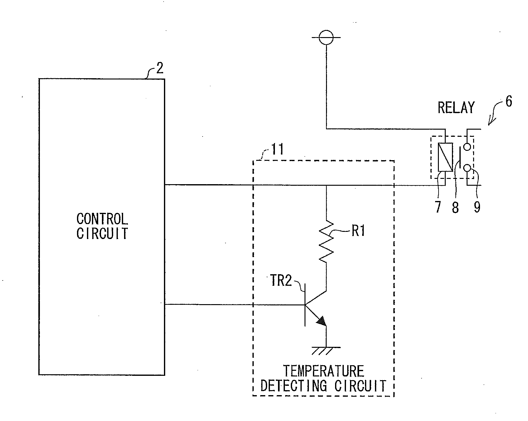
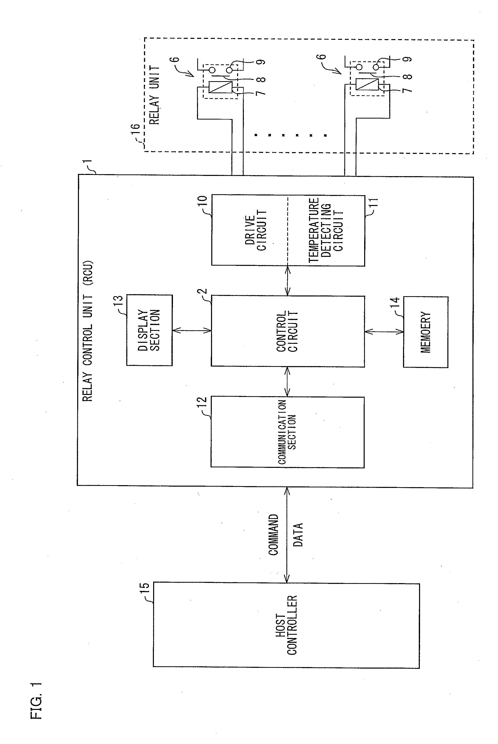
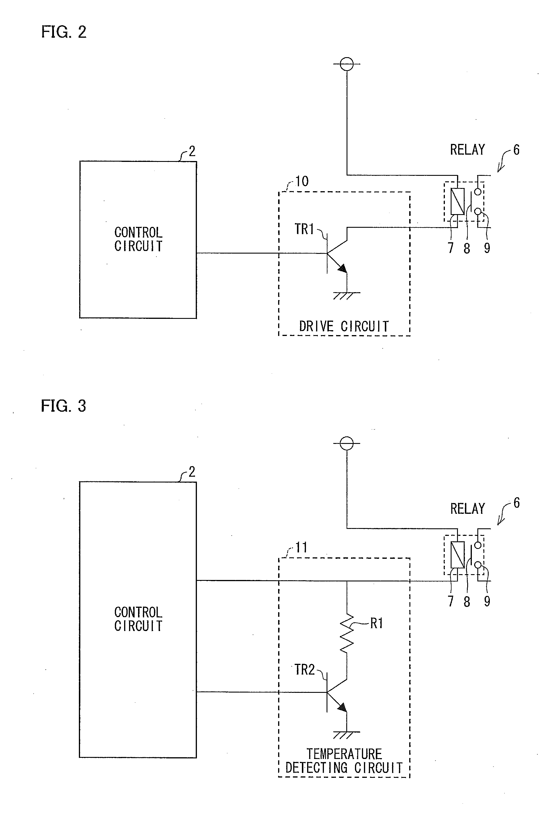
[0038]FIG. 1 is a block diagram illustrating a configuration of a relay control unit 1 (unit for controlling an electromagnetic relay) in accordance with Embodiment 1. The relay control unit 1 includes a communication section 12. The communication section 12 transmits / receives a command and data to / from a host controller 15. The relay control unit 1 further includes a control circuit 2. The control circuit 2 drives a plurality of relays 6 (electromagnetic relays), included in a relay unit 16, via respective drive circuits 10 in accordance with a command which the communication section 12 has received from the host controller 15. The control circuit 2 detects temperatures of the plurality of relays 6 via respective temperature detecting circuits 11.

[0039]Each of the plurality of relays 6 has a movable contact point 8, a fixed contact point 9, and an exciting coil 7 to which rated power is supplied from a corresponding one of the drive circuits 10 ...

embodiment 2

Relay Control Unit 1a

[0061]FIG. 12 is a block diagram illustrating a configuration of a relay control unit 1a (electromagnetic relay) in accordance with Embodiment 2. Note that identical reference numerals are given to respective members identical to those in Embodiment 1, and the members will not be described below in detail.

[0062]The relay control unit 1a includes a communication section 12. The communication section 12 transmits / receives a command and data to / from a host controller 15. The relay control unit 1a further includes a control circuit 2a. The control circuit 2a drives a plurality of relays 6 (electromagnetic relays), included in a relay unit 16, via respective drive circuits 10 in accordance with a command which the communication section 12 has received from the host controller 15. The control circuit 2 detects a weld on the plurality of relays 6 via respective temperature detecting circuits (weld detecting circuits) 11.

[0063]Each of the plurality of relays 6 has a mo...


PUM


Abstract

A unit for controlling one or more electromagnetic relays, each having a contact point and an exciting coil to which rated power is supplied so as to open and close the contact point, has a control circuit which carries out PWM control so as to keep an electromagnetic relay turned on, after turning on the electromagnetic relay by causing rated power to be supplied to an exciting coil of the electromagnetic relay, and a temperature detecting circuit that detects a resistance value of the exciting coil so as to allow the control circuit to calculate a temperature of the electromagnetic relay. The control circuit changes, depending on external information, a controlling value in accordance with which the PWM control is carried out with respect to the electromagnetic relay. The control circuit detects, from the temperature detecting circuit, a voltage corresponding to the resistance value of the exciting coil.

Description

BACKGROUND[0001]1. Technical Field[0002]The present invention relates to a unit and a method each for controlling an electromagnetic relay which opens and closes a contact point by applying an electric current to an exciting coil.[0003]2. Related Art[0004]Conventionally, there has been known a unit for controlling an electromagnetic relay which unit turns on an electromagnetic relay by supplying rated power to the electromagnetic relay and then, in order to maintain an on-state of the electromagnetic relay, controls a voltage, applied to an exciting coil, to be equal to or lower than an operating voltage and equal to or higher than a return voltage (Patent Literature 1).[0005]The unit is a relay drive circuit which turns on an electromagnetic relay by applying, to an exciting coil, a voltage equal to or higher than an operating voltage by use of a collector current with which a semiconductor switching element has been turned on. The unit is configured so as to, after turning on the ...

Claims


Application Information

Patent Timeline
IPC IPC(8): H01H47/22
CPCH01H47/22H01H47/04H01H2047/025
Inventor KINOSHITA, MASAHIROIWASAKA, HIROYUKINAKAMURA, WATARU
Owner ORMON CORPORATION
Features
  • Generate Ideas
  • Intellectual Property
  • Life Sciences
  • Materials
  • Tech Scout
  • Unparalleled Data Quality
  • Higher Quality Content
  • 60% Fewer Hallucinations
Learn More