Coded localization systems, methods and apparatus

a localization system and code technology, applied in the field of coded localization systems, methods and apparatuses, can solve the problems of reducing the accuracy of the localization and orientation of objects, affecting the achievable size, weight and power of objects, and limiting the precision of pixels with fixed system geometries, so as to achieve the effect of reducing size, weight cost and power, and superior performance, size, weight and power

Active Publication Date: 2015-08-06
ASCENTIA IMAGING
View PDF7 Cites 31 Cited by
  • Summary
  • Abstract
  • Description
  • Claims
  • Application Information

AI Technical Summary

Benefits of technology

[0008]The limitations of prior art localization imaging systems are improved as disclosed herein, where an optical array of elements is arranged more similarly to a radar system, such that the field patterns from each element or channel overlap. Mathematical weights may also be applied across the array, through embodiments of coded localization optics or specialized coded localization sensors described hereinbelow. Decoding provides the information desired, enabling optical imaging systems to perform localization tasks in a manner s...

Problems solved by technology

Estimating and detecting the 3D location and orientation of objects is a classic problem.
Numerous prior art systems have issues which negatively influence the achievable size, weight, and power, cost and precision of object 3D localization and orientation.
A fundamental issue with prior art optical digital imaging systems shown in FIG. 1 (u...

Method used


Image

  • Coded localization systems, methods and apparatus
  • Coded localization systems, methods and apparatus
  • Coded localization systems, methods and apparatus

Examples


Embodiment Construction

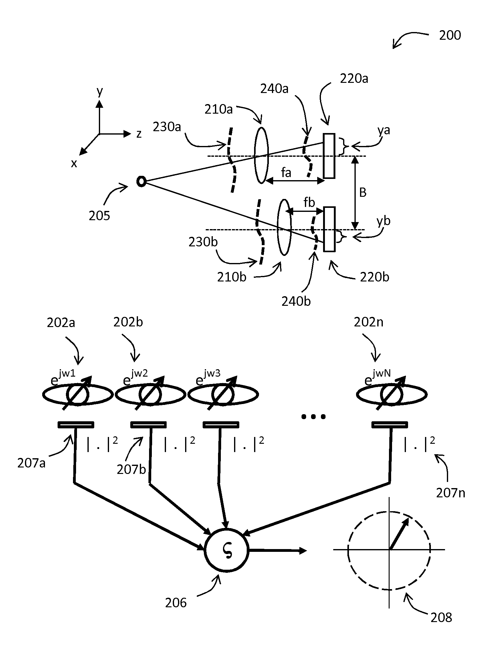
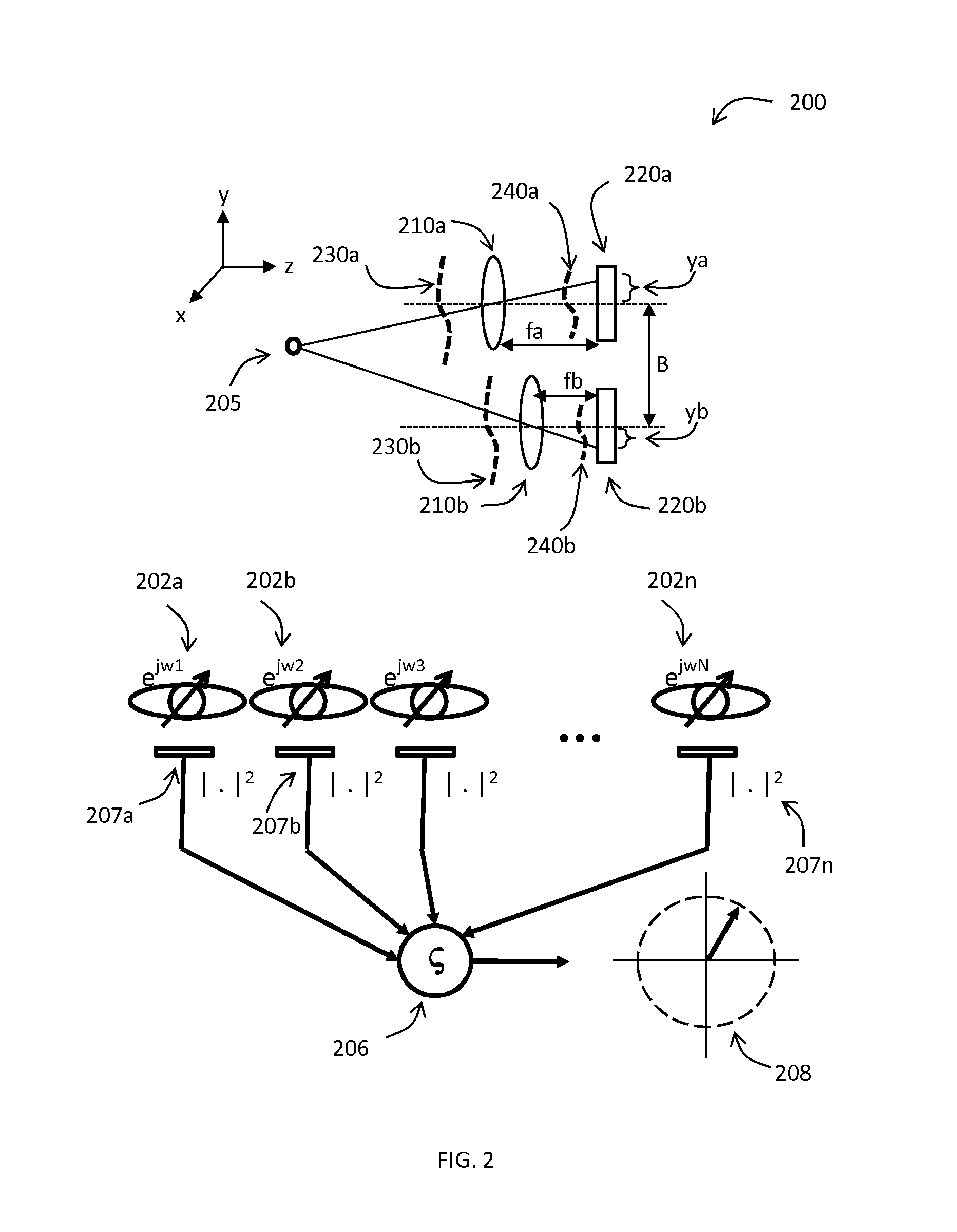
[0117]The following disclosure is organized to first present general themes, and then design methods, and finally specific applications and devices. System concepts and mathematics underlying the various embodiments, including the physical layout of optical coding and data vector formation are shown in FIGS. 2-4. Examples for applying codes to multiple-pixel and single-pixel system are shown in FIGS. 5-9. A framework for designing particular codes based on Fisher information is disclosed in FIGS. 10-12, and provides methodology for selecting a particular code for a task requirement. With the full reading and appreciation of FIGS. 2-12, specific devices may be developed. Such devices can embody several system embodiment features at the same time, and examples are provided. An example of data processing where the codes are polarization analyzer angles is shown in FIGS. 13-17. A two-pixel detector example that detects the location of a moving object is provided in FIGS. 18-20; this app...


PUM


Abstract

A coded localization system includes a plurality of optical channels arranged to cooperatively image at least one object onto a plurality of detectors. Each of the channels includes a localization code that is different from any other localization code in other channels, to modify electromagnetic energy passing therethrough. Output digital images from the detectors are processable to determine sub-pixel localization of the object onto the detectors, such that a location of the object is determined more accurately than by detector geometry alone. Another coded localization system includes a plurality of optical channels arranged to cooperatively image partially polarized data onto a plurality of pixels. Each of the channels includes a polarization code that is different from any other polarization code in other channels to uniquely polarize electromagnetic energy passing therethrough. Output digital images from the detectors are processable, to determine a polarization pattern for a user of the system.

Description

CROSS REFERENCE TO RELATED APPLICATIONS[0001]This application claims priority to U.S. provisional application Ser. No. 61 / 631,389, filed Jan. 3, 2012, entitled ANGULAR CODING FOR 3D OBJECT LOCALIZATION; U.S. provisional application Ser. No. 61 / 634,421, filed Feb. 29, 2012, entitled ANGULAR CODING FOR 3D OBJECT LOCALIZATION; U.S. provisional application Ser. No. 61 / 634,936, filed Mar. 8, 2012, entitled SYSTEMS AND METHODS FOR MOTILITY AND MOTION OBSERVATION AND DISCRIMINATION; U.S. provisional application Ser. No. 61 / 685,866, filed Mar. 23, 2012, entitled ANGULAR CODING FOR 3D OBJECT LOCALIZATION; U.S. provisional application Ser. No. 61 / 686,728, filed Apr. 11, 2012, entitled ANGULAR CODING FOR 3D OBJECT LOCALIZATION; U.S. provisional application Ser. No. 61 / 687,885, filed May 3, 2012, entitled ANGULAR CODING FOR 3D OBJECT LOCALIZATION; U.S. provisional application Ser. No. 61 / 655,740, filed Jun. 5, 2012, entitled ANGULAR CODING FOR 3D OBJECT LOCALIZATION AND MOTION DETECTION; U.S. p...

Claims


Application Information

Patent Timeline
IPC IPC(8): G01B11/00G05D1/02
CPCG01S19/48G05D1/02G01B11/002G01S5/16G06T7/70G01S19/485G01S19/42G05D1/0251G05D1/0278
Inventor DOWSKI, EDWARD R.SISSOM, BRADLEYJOHNSON, GREGORY
Owner ASCENTIA IMAGING
Why Eureka
Try Eureka