

X-ray imaging system and image processing method
a phase-contrast imaging and image processing technology, applied in the field of x-ray imaging system and image processing method, can solve the problems of significant impairing image quality, salt and pepper noise regions cannot be correctly recognized through conventional methods, and different phase images and small-angle scattering images acquired through phase-contrast imaging with gratings are unsatisfactory for imaging, etc., to enhance the stability and speed of post-processing, and facilitate diagnosis and examination.
Image

Examples
first embodiment
[0041]A first embodiment of the present invention will now be described with reference to the accompanying drawings.
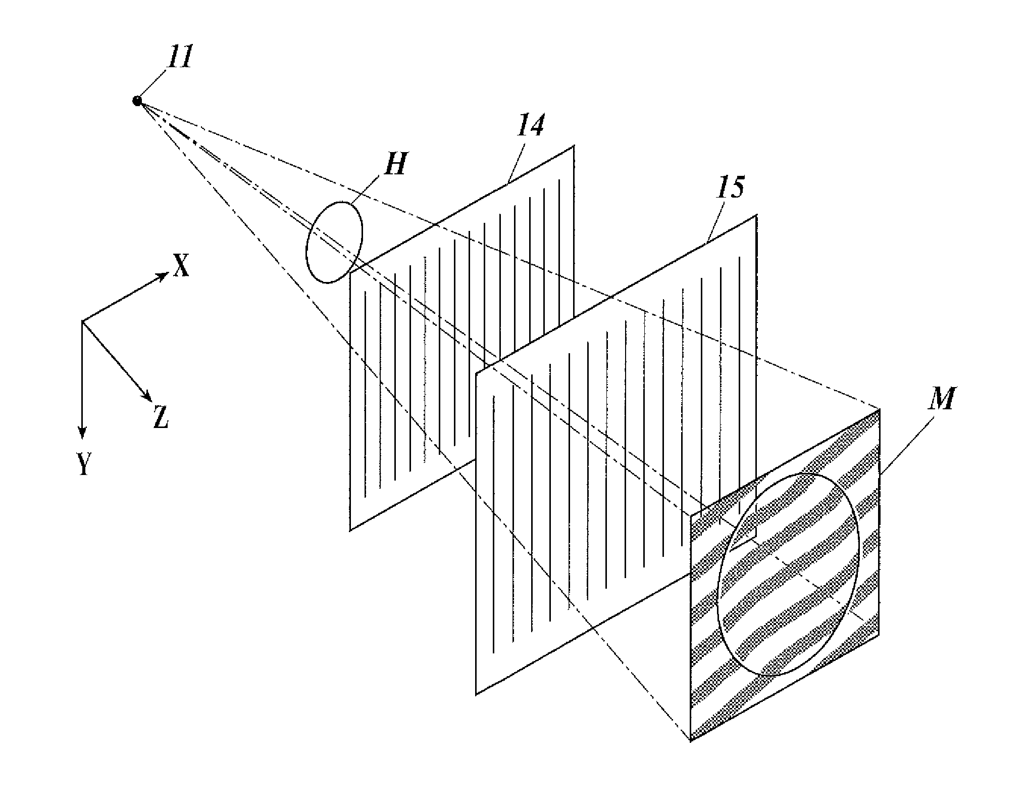
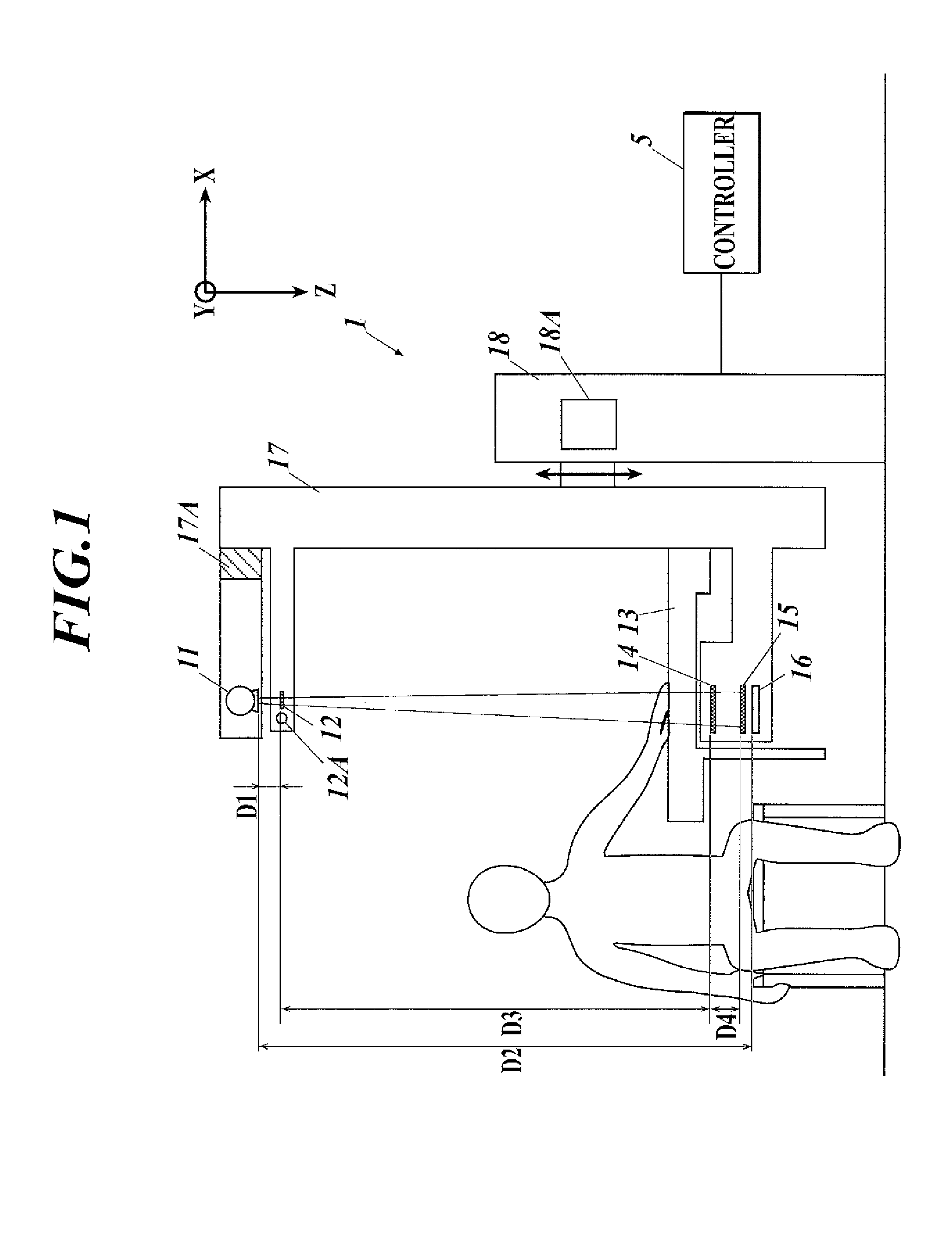
[0042]FIG. 1 illustrates an X-ray imaging system according to the first embodiment. The X-ray imaging system includes an X-ray imaging apparatus 1 and a controller 5. The X-ray imaging apparatus 1 performs X-ray imaging with a Talbot-Lau interferometer. The controller 5 generates a reconstructed image of an object from a plurality of moire stripe images acquired through the X-ray imaging.
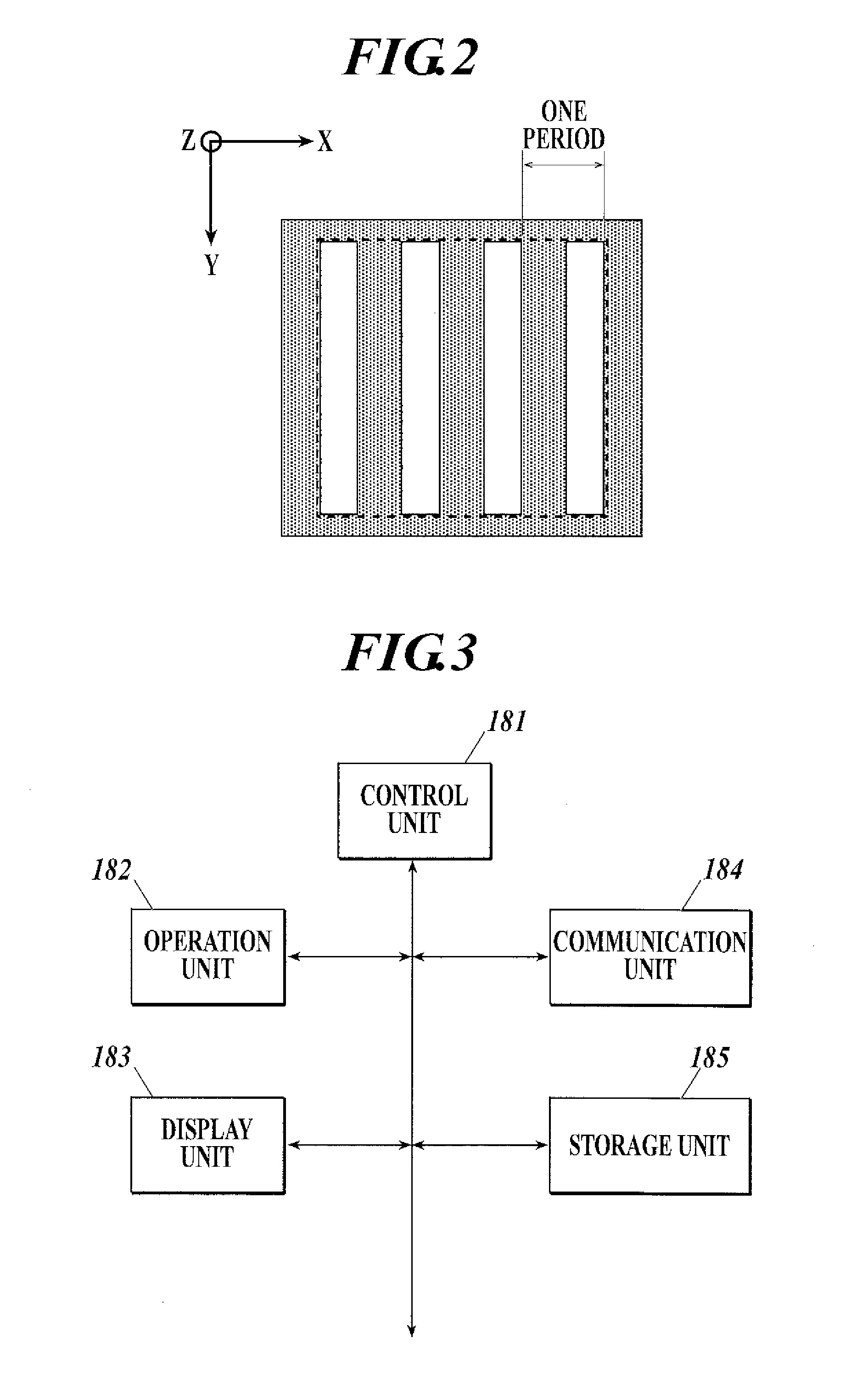
[0043]With reference to FIG. 1, the X-ray imaging apparatus 1 includes an X-ray source 11, a multislit grating 12, an object table 13, a first grating 14, a second grating 15, an X-ray detector 16, a support unit 17, and a main unit 18.
[0044]The X-ray imaging apparatus 1 is of an up-right type in which the X-ray source 11, the multislit grating 12, the object table 13, the first grating 14, the second grating 15, and the X-ray detector 16 are disposed along the Z or gravity direction. ...
second embodiment
[0174]A second embodiment of the present invention will now be described.
[0175]The detection process of system noise regions based on characteristic values of BG moire stripe images has been described in the first embodiment. The second embodiment describes an example detection process of system and object noise regions based on characteristic values of object moire stripe images.
[0176]The configuration of the X-ray imaging system and imaging control process according to the second embodiment are the same as those according to the first embodiment, and the redundant description thereof will not be repeated here.
[0177]During actual imaging of an object, the radiation exposure of the object may be reduced by applying an X-ray protective fabric over the object or narrowing the radiation field aperture to decrease the size of the radiation field to a size smaller than that for the imaging of BG moire stripe images. In such cases, salt and pepper noise occurs in regions of low X-ray inte...
third embodiment
[0187]A third embodiment of the present invention will now be described.
[0188]The third embodiment describes the calculation of a noise index for an image reconstructed on the basis of the characteristic values of the BG moire stripe images and the object moire stripe images and the detection of regions of system noise and object noise based on the noise index for the reconstructed image.
[0189]The configuration of an X-ray imaging system and imaging controlling process according to the third embodiment are identical to those according to the first embodiment, and thus, the redundant descriptions thereof will not be repeated here. An image generating / displaying process (image generating / displaying process C) according to the third embodiment will be described now.
[0190]FIG. 19 is a flowchart illustrating the image generating / displaying process C carried out by the controller 5 according to the third embodiment. The image generating / displaying process C is carried out by the control u...
PUM