Encoded light-activated illumination

a technology of modulated light and illumination, applied in the direction of transmission system, close-range type system, instruments, etc., can solve the problems of depleting the battery of the lighting unit, affecting the illumination effect, so as to achieve constant average on time and conserve battery energy

a technology of modulated light and illumination, applied in the direction of transmission system, close-range type system, instruments, etc., can solve the problems of depleting the battery of the lighting unit, affecting the illumination effect, so as to achieve constant average on time and conserve battery energy

US20150245448A1Inactive Publication Date: 2015-08-27READLER BLAINE CLIFFORD

Image

  • Encoded light-activated illumination
  • Encoded light-activated illumination
  • Encoded light-activated illumination

Examples


Embodiment Construction

[0035]According to the invention described here, detached lighting units are made to selectively activate only at specific times as controlled by the light of a capable handheld flashlight. The light of the flashlight is encoded with information, and in this way the lighting units do not respond to normal light, whether the ambient light of daytime, or miscellaneous stray light from car headlights, neighbors lights, etc.

Source Flashlight and Target Detached Lighting Unit, FIG. 1

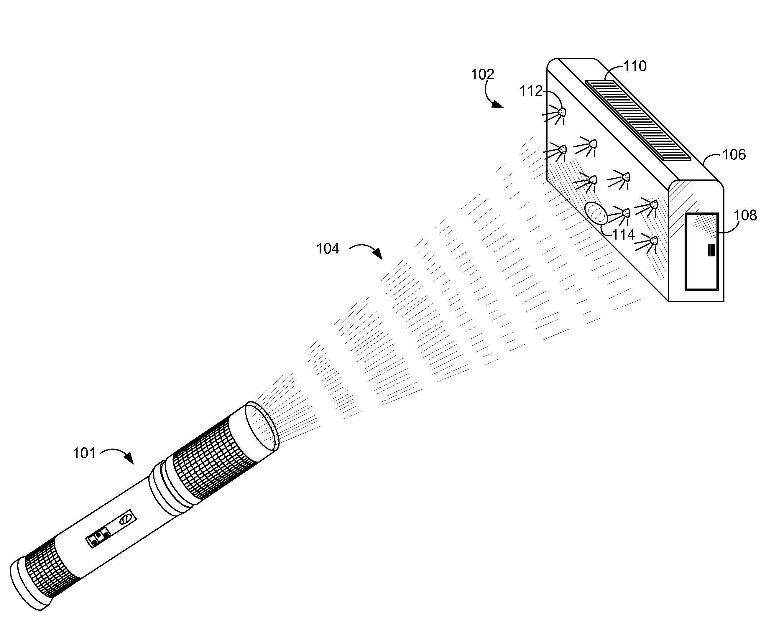
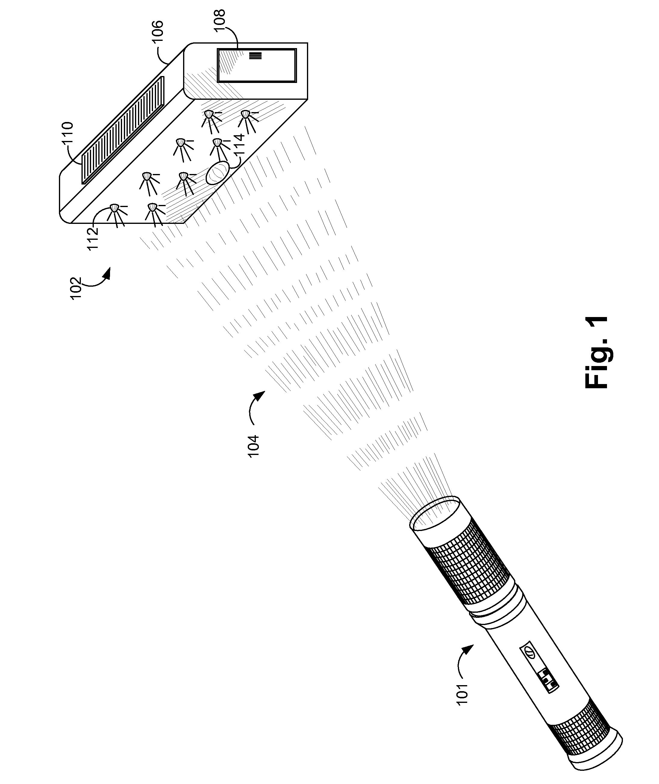
[0036]FIG. 1 shows an embodiment 101 of the encoded-light source flashlight activating an embodiment 102 of the target detached lighting unit using encoded light 104. The detached lighting unit 102 is contained within enclosure 106, and includes a battery compartment as accessed by removable cover piece 108. Optional solar cell panel 110 allows recharging of batteries during daylight. LED 112 is one of an array for providing illumination. Optical sensor input 114 provides a means for the detached lighting uni...


PUM


Abstract

A method for controlling detached lighting units uses source light of a capable flashlight to communicate information. The capable flashlight encodes an ID Tag in modulated light, and the detached lighting units recognize the specific ID Tag and responds, for example by activating and creating illumination. A user can illuminate selected areas by shining the beam of the flashlight on detached lighting units to selectively activate them, and since the detached lighting units only respond to the encoded light, unintended activation is avoided. In addition to the encoded ID Tag, mode information can be included such that the detached lighting units can respond in a number of ways, such as selected periods of activation. Stored ID Tags can be transferred and thus shared using the same modulated light. ID Tags can be randomly re-assigned, and the new value shared among other flashlights and detached lighting units, creating a coordinated set.

Description

CROSS-REFERENCE TO RELATED APPLICATIONS[0001]Not Applicable.SEQUENCE LISTING[0002]Not ApplicableBACKGROUND[0003]1. Field of Invention[0004]This invention relates to remotely controlled illumination, and specifically to remote control of illumination via modulated light of a flashlight.[0005]2. Description of Prior Art[0006]Outdoor lighting traditionally consists of light fixtures powered by AC mains, mounted to outside walls, and activated either by wall-mounted switches or co-located motion sensors. These methods serve admirably for areas in the near proximity of a house or other structure connected to AC power such as a garage, but leave areas beyond the reach of the structure-mounted lighting in darkness.[0007]With the advent of energy efficient LEDs and economical photo-electric power cells, self-contained solar-powered lighting systems have become popular. However, because of the limited solar charging energy available each day, and the economical limits of storage battery capa...

Claims


Application Information

Patent Timeline
27 Aug 2015
Publication
US20150245448A1
IPC
H05B37/02; G08C23/00; H05B33/08; H04B10/116; H05B44/00
CPC
H05B37/0272; H05B33/0842; G08C23/00; H04B10/116; G08C17/00; H05B47/195
Inventors
READLER, BLAINE CLIFFORD