
Hopper structure, dehumidification plant and method for dehumidifying granular plastic material

a technology of plastic material and hopper, which is applied in the direction of drying machines, lighting and heating equipment, furnaces, etc., can solve the problems of poor quality final products, adversely affecting the characteristics of manufactured articles or final products, and products with inadequate mechanical characteristics, so as to prevent or drastically reduce the formation of thermal gradients, the effect of constant residence tim

Active Publication Date: 2014-07-01
MORETTO SPA
View PDF14 Cites 15 Cited by
  • Summary
  • Abstract
  • Description
  • Claims
  • Application Information

AI Technical Summary

Benefits of technology

[0038]The main object of the present invention is to provide a hopper structure for the dehumidification of granular plastic material that is capable of ensuring a substantially constant residence time in a hopper of the plastic material granules and to prevent or drastically reduce the formation of thermal gradients of the granules being situated at a same level in the dehumidification hopper.
[0040]Another object of the present invention is to provide a dehumidification plant which is suitable for effectively achieving the dehumidification of granular plastic material with reduced energy consumption compared to the dehumidification plants of the state of the art.
[0041]Another object of the present invention is to provide a dehumidification method that allows ensuring a uniform dehumidification of the plastic material granules.

Problems solved by technology

If the molecular chains should break, as will be understood, poor quality final products would be obtained; in any case, products would be obtained with inadequate mechanical characteristics, considering that bubbles, blowholes, coloration non-uniformity and other undesired phenomena are often generated, ascribable to the presence of water in the starting granules.
If, instead, the granules had different temperatures in radial direction, there would be different diffusion constants D, and different dehumidification degrees would be obtained in the granules, which would negatively affect the characteristics of the manufactured article or final product.
Nevertheless, with one such hopper structure, in the plastic material granules located at a same level, i.e. in the radial direction, one obtains an undesired thermal gradient, which can involve non-uniform levels of dehumidification of the granules, i.e. granules are obtained having different moisture levels, which can compromise the qualitative characteristics of the final manufactured product.
In plants for working plastic material granules, the granules should not be subjected to thermal stress, otherwise their rheological properties can be negatively affected.
Moreover, with the hopper taught by such US patent, a satisfying dehumidification with a reduced energy consumption cannot be obtained.

Method used


Image

  • Hopper structure, dehumidification plant and method for dehumidifying granular plastic material
  • Hopper structure, dehumidification plant and method for dehumidifying granular plastic material
  • Hopper structure, dehumidification plant and method for dehumidifying granular plastic material

Examples


Embodiment Construction

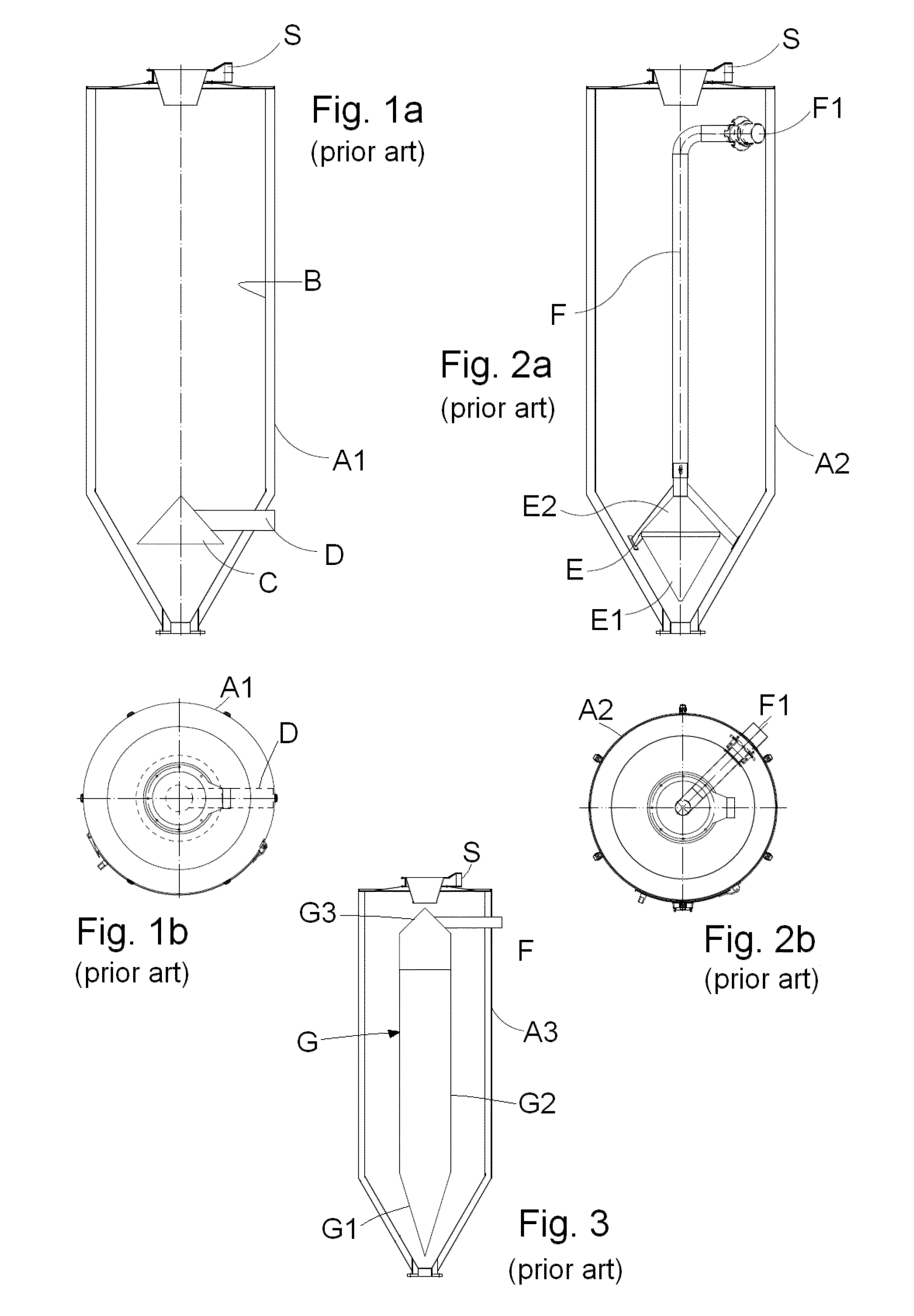
[0067]As specified above, various hopper structures have already been proposed, such as that of the hopper A1 illustrated in FIGS. 1a and 1b, which comprises a cylindrical body terminating with a tapered lower portion delimiting a treatment chamber B for a granular plastic material to be treated. At the upper part (upper in use) of the tapered lower portion, a hollow, conical diffuser insert C is provided with apex turned upward. The insert interior is in fluid communication with a radial insufflation duct D, in turn in communication with an external treatment fluid source (hot and dry air), typically a dryer.

[0068]During the dehumidification process, therefore, the air is fed to the insufflation duct D and comes into contact with the material present in the treatment chamber B at the lower edge or conical base of the insert C, in order to rise inside the treatment chamber until it exits at the top of the hopper through a suitable air discharge mouth S. With a hopper of this type, o...


PUM

PropertyMeasurementUnit
temperatureaaaaaaaaaa
radiusaaaaaaaaaa

Abstract

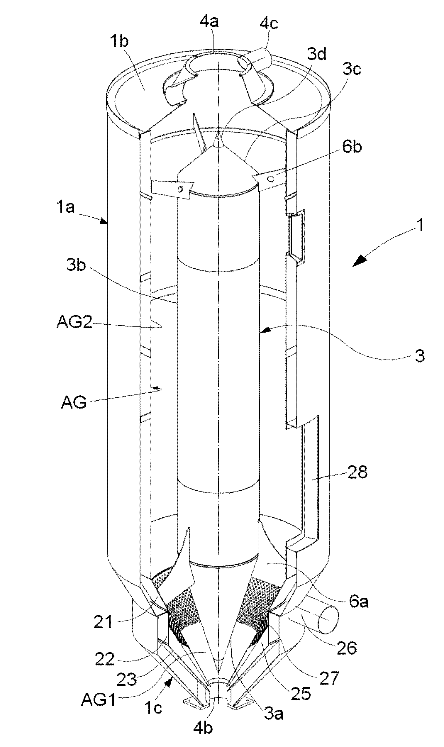
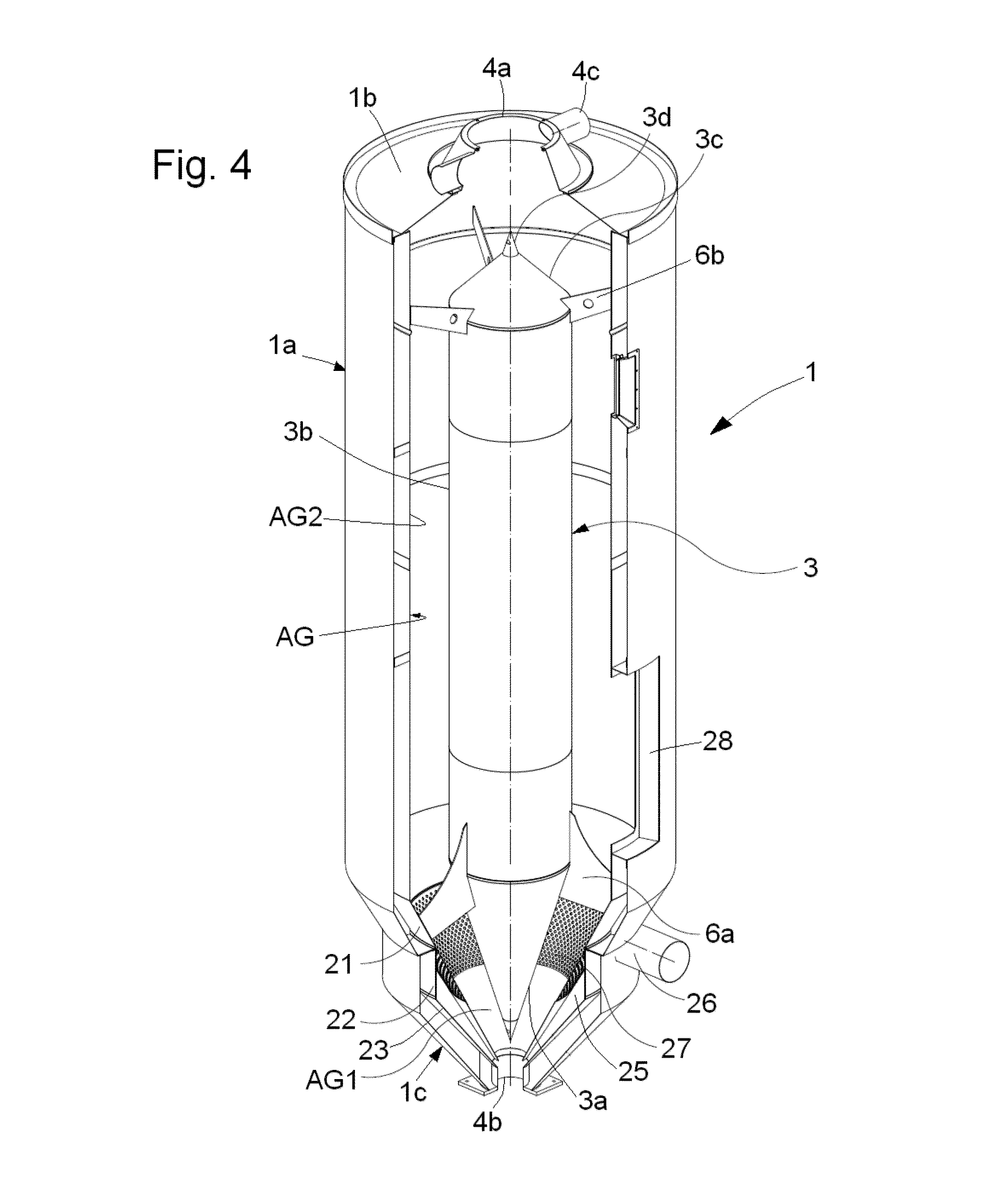
A hopper for dehumidification of granular plastic material by a dehumidifying fluid includes a main body, having a top wall with an opening for the granular plastic material; at least one discharge opening for the dehumidifying fluid provided on the main body or the top wall, a tapered lower section with a discharge opening for the dehumidified granular plastic material, a fluid-sealed insert member delimiting an annular air space with the main body and the tapered lower section, and at least one dehumidifying fluid feed duct to the annular air space, the lower tapered section comprising at least one pair of walls to delimit at least one chamber that is outside the annular air space and in fluid communication therewith, the at least one chamber being feedable with dehumidifying fluid from the at least one feed duct oriented tangentially or parallel to an enclosing wall.

Description

FIELD OF INVENTION[0001]The present invention relates to a hopper structure and a plant for treating granular plastic material, and a method for dehumidifying granular plastic material in a hopper.[0002]In the present patent application, the terms “granules” or “granular” are meant to indicate chips, small laminas or plates produced by the grinding-crushing of plastic material in slab, sheet, film or similar form.[0003]The term “hopper” is intended to mean any type of container, sometimes also called a silo, having a cross section, e.g. circular, square or rectangular, and terminating at its lower part with a tapered discharge section equipped with a discharge mouth, usually controlled by a suitable discharge valve.BACKGROUND OF THE INVENTION[0004]As is known, in the process of transformation of most plastic materials into granules or granular materials, a very important treatment consists of the process of dehumidification of the plastic material granules, i.e. the removal of the w...

Claims


Application Information

Patent Timeline
Patent Type & Authority Patents(United States)
IPC IPC(8): F26B3/00
CPCF26B9/063F26B17/1441B29B13/065B29B9/16B29B13/06B29C31/02B65D88/26B65G3/04
Inventor MORETTO, RENATO
Owner MORETTO SPA
Learn More