

Image printing apparatus
Inactive Publication Date: 2007-02-22
KONICA MINOLTA BUSINESS TECH INC
View PDF1 Cites 15 Cited by
- Summary
- Abstract
- Description
- Claims
- Application Information
AI Technical Summary
Benefits of technology
[0017] In consideration of the above situation, the present inventors compared and examined a case wherein a stabilized speed was obtained by acceleration from a low speed and a case wherein a stabilized speed was obtained by deceleration from a high speed. As a result, the present inventors found that stabilizing a speed by deceleration from a high speed could shorten the time required to stabilize a speed as compared with the case wherein a speed was stabilized by acceleration from a low speed, could shorten the time accompanied by speed fluctuations, and was suitable for the elimination of a convey time shift, thereby reaching the present invention.
[0018] The present invention can therefore provide an image printing apparatus which can transfer toner images to predetermined positions on image recording sheets at the image transfer position without causing any image shift between the image recording sheets by conveying each image recording sheet with high accuracy so as to keep constant the convey time required for each image recording sheet to reach the image transfer position from the registration roller unit.
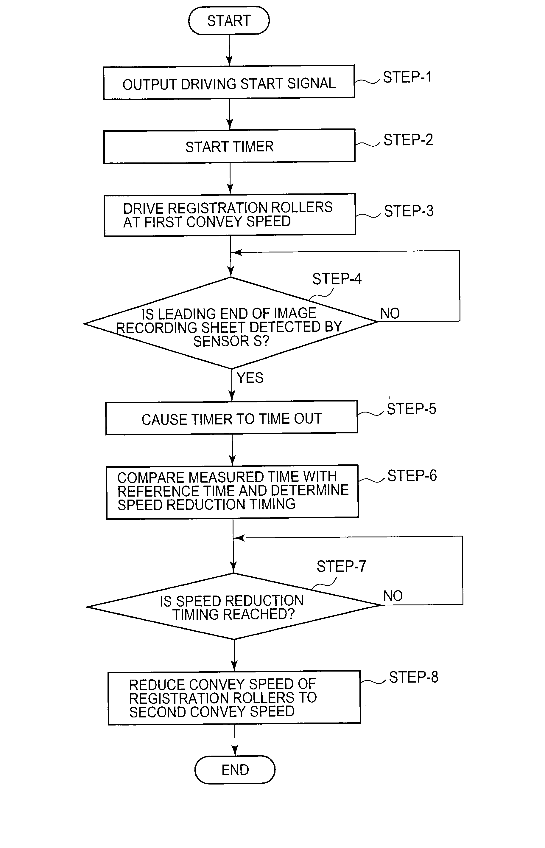
[0019] According to a primary aspect of the present invention, there is provide an image printing apparatus comprising an image printing unit which forms a toner image, an image carrier which carries the toner image formed by the image printing unit, an image transfer member which transfers the toner image carried on the image carrier onto an image recording sheet, registration roller unit which convey the image recording sheet toward an image transfer position at which the toner image is transferred onto the image recording sheet by the image transfer member, a sensor which is provided between the registration roller unit and the image transfer position to detect the image recording sheet, and a control unit which controls driving of the registration roller unit, wherein the control unit performs control to start driving the registration roller unit at a first sheet convey speed higher than a linear speed of a surface of the image carrier, measure a time required until a leading end of a conveyed image recording sheet is detected by the sensor after a driving signal for starting driving of the registration roller unit is output, compare the measured time with a preset reference time, determine, on the basis of a comparison result, a timing at which the sheet convey speed of the registration roller unit is reduced from the first sheet convey speed to a second sheet convey speed, reduce the sheet convey speed of the registration roller unit from the first sheet convey speed to the second sheet convey speed at the determined timing, and convey the image recording sheet to the image transfer position at the second sheet convey speed.
[0021] As is obvious from each aspect described above, according to the present invention, it suffices to perform only two-step drive control, i.e., starting the driving of the registration roller unit at the first sheet convey speed higher than the linear speed of the surface of the image carrier, measuring the time required until the leading end of a conveyed image recording sheet is detected by the sensor after a driving signal for the registration roller unit is output, and reducing the sheet convey speed of the registration roller unit to the second sheet convey speed at the timing based on the measurement result. This eliminates the necessity to perform complicated control of the technique disclosed in patent reference 1 and allows easy control.
[0022] In addition, the time required for each image recording sheet to reach the image transfer position can be made constant, and each image recording sheet can be transferred to a predetermined position with high accuracy. This can eliminate the problem of an image shift between image recording sheets. Furthermore, since the driving of the registration roller unit is started at the first sheet convey speed higher than the linear speed of the surface of the image carrier, a high-speed image printing apparatus with high productivity can be provided.
[0023] In other words, even variations in the start of driving of the registration roller unit, a delay in conveyance of an image recording sheet due to a slip, variations in initial sheet convey speed, and variations in the stop position of an image recording sheet at the nip portion of the registration roller unit can be easily corrected. This makes it possible to convey each image recording sheet from the registration roller unit to the image transfer position in a predetermined period of time at a predetermined timing.
Problems solved by technology
Even if, however, the driving of the registration roller unit is tried to be controlled at a predetermined sheet convey speed, the time taken to convey an image recording sheet to the image transfer position varies due to speed fluctuations caused by power fluctuations in a drive source which drives the registration roller unit.
In addition, slip occurs between an image recording sheet and the registration roller unit due to the wear of the surfaces of the registration roller unit over time or the like.
As a result, even if the driving of the registration roller unit is started, the conveyance of the image recording sheet is not immediately started, resulting in a delay of the time taken to convey the image recording sheet to the image transfer position.
If the convey time required for an image recording sheet to reach the image transfer position is caused to become unstable due to such various factors, a toner image cannot be transferred onto a predetermined position on the image recording sheet.
As a result, the quality of printed images becomes poor.
According to this technique, since there is an area where an image recording sheet is conveyed at a low speed, the productivity of copies is low.
That is, the technique is not suitable for high-speed image printing operation, i.e., a high-speed apparatus.
In addition, if a stepping motor is used to change the sheet convey speed, it takes much time to stabilize the speed, and there is a time accompanied by speed fluctuations.
As a consequence, the accuracy of the time taken to convey an image recording sheet to the image transfer position deteriorates to cause a positional shift.
For this reason, the technique disclosed in patent reference 1 is designed to eliminate speed fluctuations by changing the speed in multiple steps, but cannot satisfy the requirement for accurate conveyability.
However, no consideration is given to a convey time shift in a convey step on the downstream side of the registration roller unit.
However, since a convey time shift on the downstream side of the registration roller unit cannot be corrected, the positional shift of an image printed on the image recording sheet cannot be eliminated.
Method used
View moreImage
Smart ImageViewing Examples

Examples
experimental example
[0118] The control on the registration roller unit 23 in the embodiment of the present invention was performed to print images on 3,000 image recording sheets, and the distances from the leading ends of the respective image recording sheets to the positions where toner images were formed were measured. If the difference between the measured maximum and minimum distances is regarded as a positional shift amount, the maximum positional shift amount is 0.2 mm. The level of this positional shift satisfies the condition of accuracy required for a quick printer.
Login to View More PUM
 Abstract
The present invention provides an image printing apparatus which comprises registration roller unit which convey an image recording sheet toward an image transfer position at which the toner image is transferred onto the image recording sheet, a sensor which is provided between the registration roller unit and the image transfer position to detect the image recording sheet, and a control unit which controls driving of the registration roller unit. In order to make the time required for each image recording sheet to reach the image transfer position constant, the image printing apparatus is adapted to start the driving of the registration roller unit at the first sheet convey speed higher than the linear speed of the surface of the image carrier, measure the time required until the leading end of a conveyed image recording sheet is detected by the sensor after a driving signal for the registration roller unit is output, and reduce the sheet convey speed of the registration roller unit to the second sheet convey speed at the timing based on the measurement result.
Description
CROSS-REFERENCE TO RELATED APPLICATION [0001] This application makes reference to, incorporates the same herein, an claims all benefits accruing under 35 U.S.C. §119 from an application for IMAGE PRINTING APPARATUS earlier filed in the Japanese Patent Office on Aug. 22, 2005, and there duly assigned the application No. 2005-239733. BACKGROUND OF THE INVENTION [0002] 1. Field of the Invention [0003] The present invention relates to an image printing apparatus such as a copying machine, printer, or facsimile apparatus and, more particularly, to an image printing apparatus which can convey an image recording sheet to an image transfer position at a constant arrival time so as to transfer a toner image carried on an image carrier onto a predetermined position on the image recording sheet with high accuracy. [0004] 2. Description of Related Art [0005] An image printing apparatus designed to transfer a toner image carried on an image carrier such as a photosensitive drum or an intermediat...
Claims
Login to View More Application Information
Patent Timeline
 IPC IPC(8): G03G15/00
CPCG03G2215/00409G03G2215/00599G03G15/235G03G15/6564
InventorISHIDA, YUJIROHAMAYA, SATOSHIISOHARA, HIDEO
OwnerKONICA MINOLTA BUSINESS TECH INC