
Control system and method for motor vehicles

Inactive Publication Date: 2004-05-06
TOYOTA JIDOSHA KK
View PDF2 Cites 38 Cited by
  • Summary
  • Abstract
  • Description
  • Claims
  • Application Information

AI Technical Summary

Benefits of technology

[0009] With this arrangement, torque shocks can be reduced as compared to when the internal combustion engine is controlled to start and run at the idle speed without considering the inertia value.
[0027] Also, it is preferable that the motor be capable of generating electric power, and that the transition control be performed at the time of stopping the motor when the motor is generating electric power using driving power from the output shaft. Thus, it is possible to reduce torque shocks, which may occur during the power generation by the motor.

Problems solved by technology

With this control system, however, although interference between the idle speed control and the engine speed control does not occur when controlling the rotation speed of the output shaft of the internal combustion engine, abrupt changes in torque (i.e., torque shocks) may occur at the output shaft during an engine start.
Thus, it is likely that torque shocks occur at the output shaft during an engine start.

Method used


Image

  • Control system and method for motor vehicles
  • Control system and method for motor vehicles
  • Control system and method for motor vehicles

Examples


Embodiment Construction

the PREFERRED EMBODIMENTS

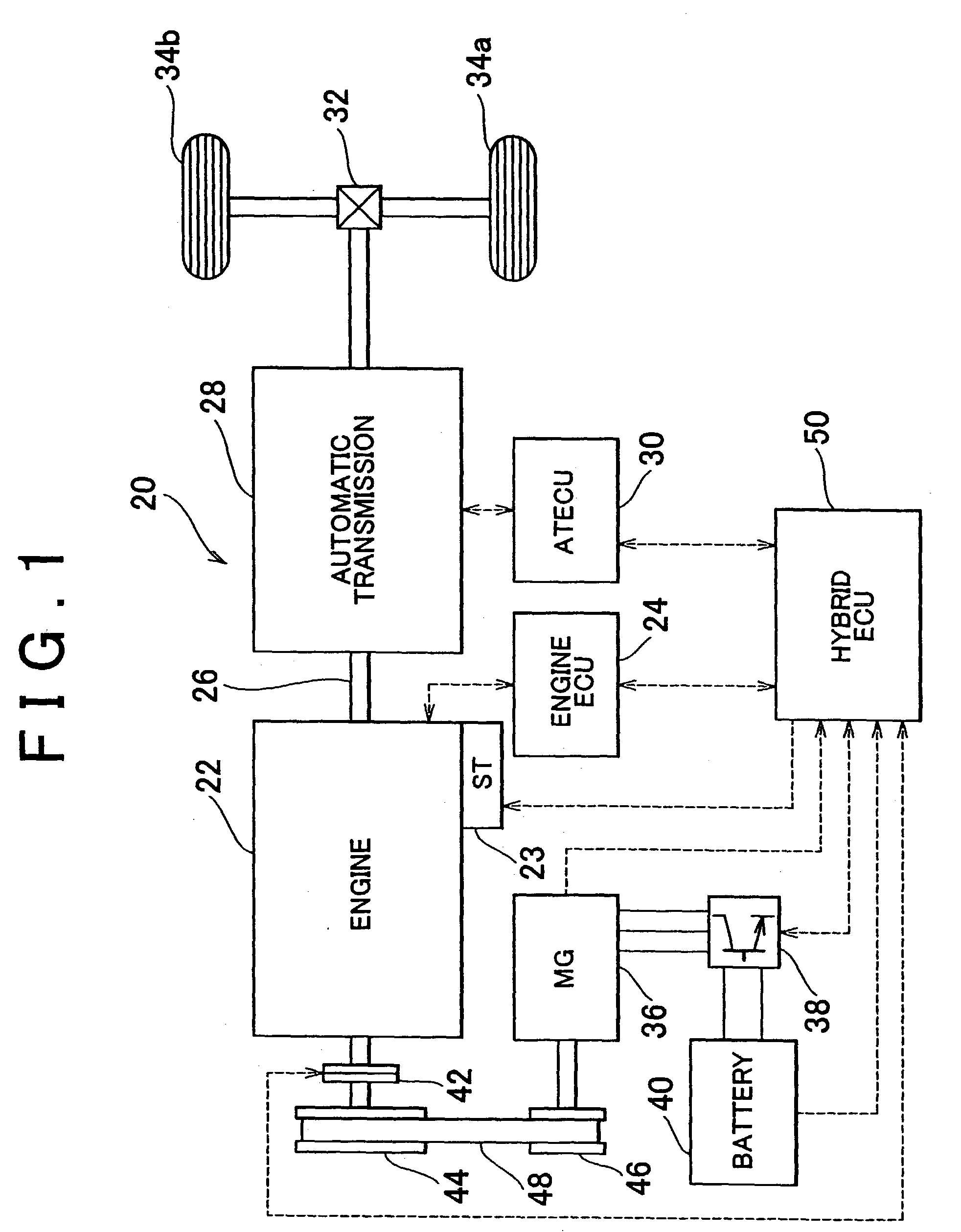
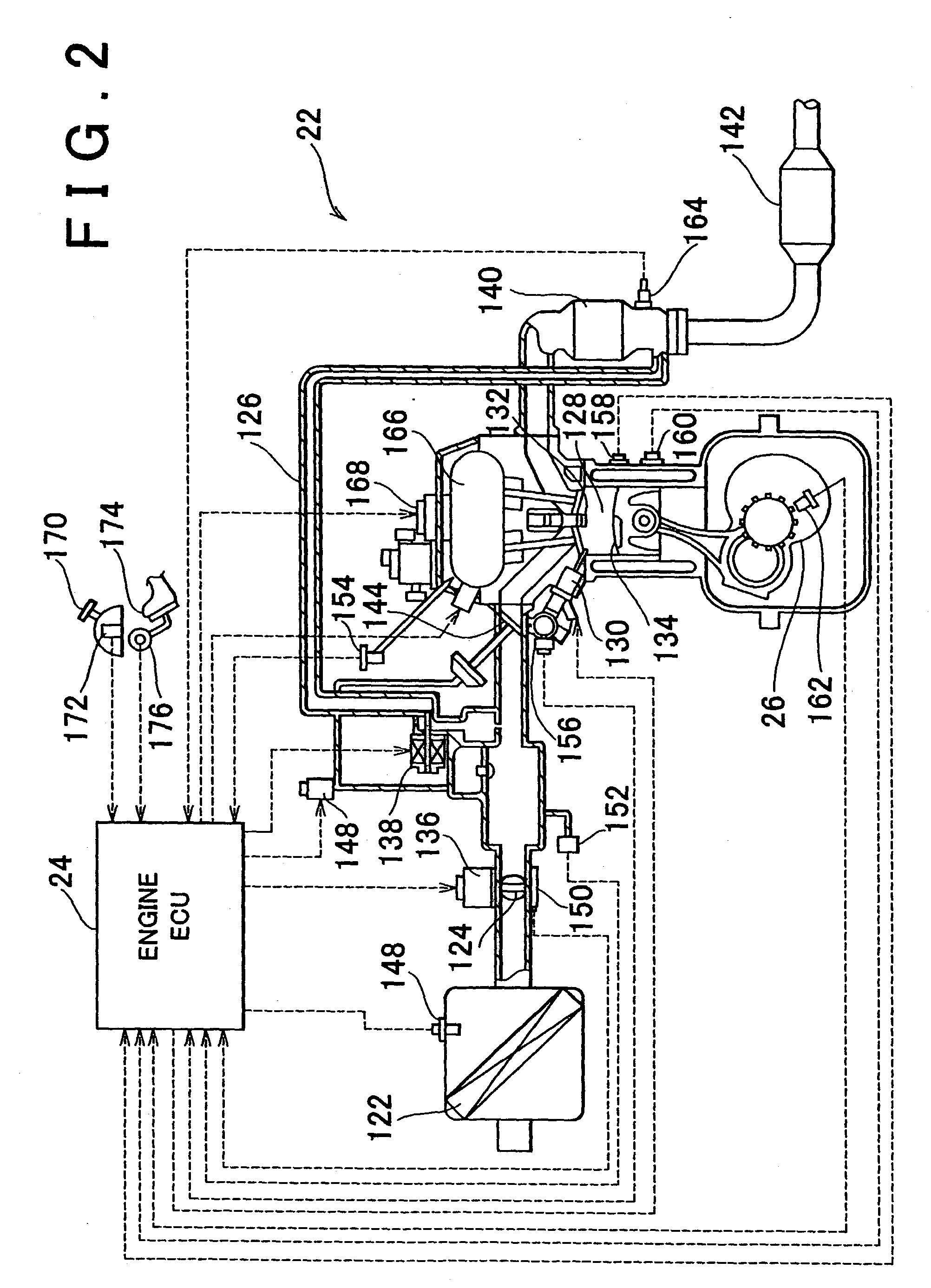
[0042] Next, an exemplary embodiment of the invention will be described with reference to the accompanying drawings. FIG. 1 is a block diagram schematically showing the configuration of a hybrid vehicle 20 incorporating a control system according to a first embodiment of the invention. As shown in the drawing, the hybrid vehicle 20 includes an engine 22 that runs using gasoline, an engine electronic control unit (hereinafter referred to as "engine ECU") 24 for controlling the engine 22, an automatic transmission 28 that changes the rotation speed output from the engine 22 to the crankshaft 26 and transmits power from the engine 22 to driven wheels 34a and 34b via a differential gear 32 at the changed rotation speed, an automatic transmission electronic control unit (hereinafter referred to as "AT ECU") 30 which controls shifting of the automatic transmission 28, a motor generator 36 which both provides and receives driving power to and from the crankshaft 26...


PUM


Abstract

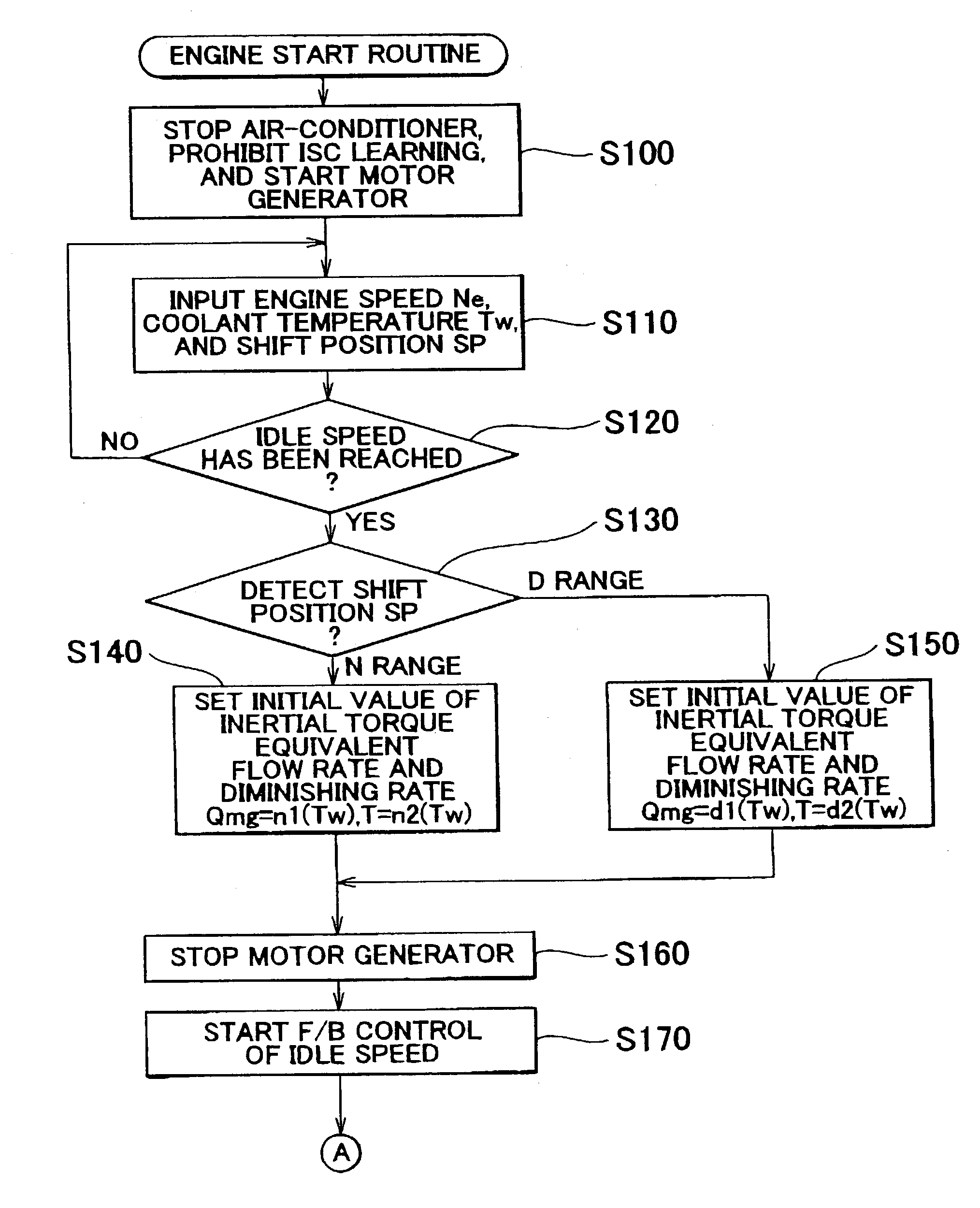
The electronic control unit sets an initial value of an inertia torque equivalent flow rate Qmg as an air flow equivalent to an inertia torque that acts on rotational elements related to a crankshaft 26, and a diminishing rate thereof, based on a shift position SP and coolant temperature Tw after the engine is cranked by a motor generator and the engine speed reaches an idle speed. The electronic control unit controls an the engine speed using an idle speed maintaining flow rate Qisc which is obtained by subtracting the inertia torque equivalent flow rate Qmg from a target idle speed maintaining flow rate Qisc*.

Description

INCORPORATION BY REFERENCE[0001] The disclosure of Japanese Patent Application No. 2002-211031 filed on Jul. 19, 2002, including the specification, drawings and abstract is incorporated herein by reference in its entirety.[0002] 1. Field of Invention[0003] The invention relates to a control system and method for a motor vehicle. More particularly, the invention relates to a control system and method for a motor vehicle including an internal combustion engine and a motor connected to an output shaft of the internal combustion engine.[0004] 2. Description of Related Art[0005] Of such control systems, for example, Japanese Laid-opened Patent Publication No. 2000-297668 discloses a control system which controls engine speed using a motor generator during engine start while prohibiting idle speed control of an internal combustion engine, thus preventing interference between the idle speed control and the engine speed control with the motor generator.[0006] With this control system, howev...

Claims


Application Information

Patent Timeline
IPC IPC(8): B60L50/10B60L50/16F02N15/00F02D17/00F02D29/00F02D29/02F02D31/00F02D41/02F02D41/06F02D41/08F02D41/14F02D41/16F02D41/26F02D41/30F02D41/34F02D45/00F02N11/04F02N11/08
CPCF02D41/009F02D41/021F02D41/0225F02D41/06F02D41/062Y10T477/675F02D41/16F02D2250/18F02N11/04F02N11/0814Y02T10/48F02D41/08Y02T10/40
Inventor MITSUTANI, NORITAKEUCHIYAMA, TOMOYUKI
Owner TOYOTA JIDOSHA KK
Learn More