Knee traction apparatus

a technology of traction apparatus and knee joint, which is applied in the field of knee traction apparatus, can solve problems such as pain and inflammation, and achieve the effects of reducing manufacturing costs, efficient limiting the bending angle of the knee joint, and facilitating manufacturing

Active Publication Date: 2015-10-01
CHANGEUI MEDICAL
View PDF3 Cites 4 Cited by
  • Summary
  • Abstract
  • Description
  • Claims
  • Application Information

AI Technical Summary

Problems solved by technology

However, bones, ligaments, and the like may be injured due to a degenerative change or injury of cartilages that protect joints, which may lead to inflammations and pain, that is, arthritis.

Method used


Image

  • Knee traction apparatus
  • Knee traction apparatus
  • Knee traction apparatus

Examples


Embodiment Construction

[0053]Reference will now be made in detail to exemplary embodiments of the present invention, examples of which are illustrated in the accompanying drawings, wherein like reference numerals refer to the like elements throughout. Exemplary embodiments are described below to explain the present invention by referring to the figures.

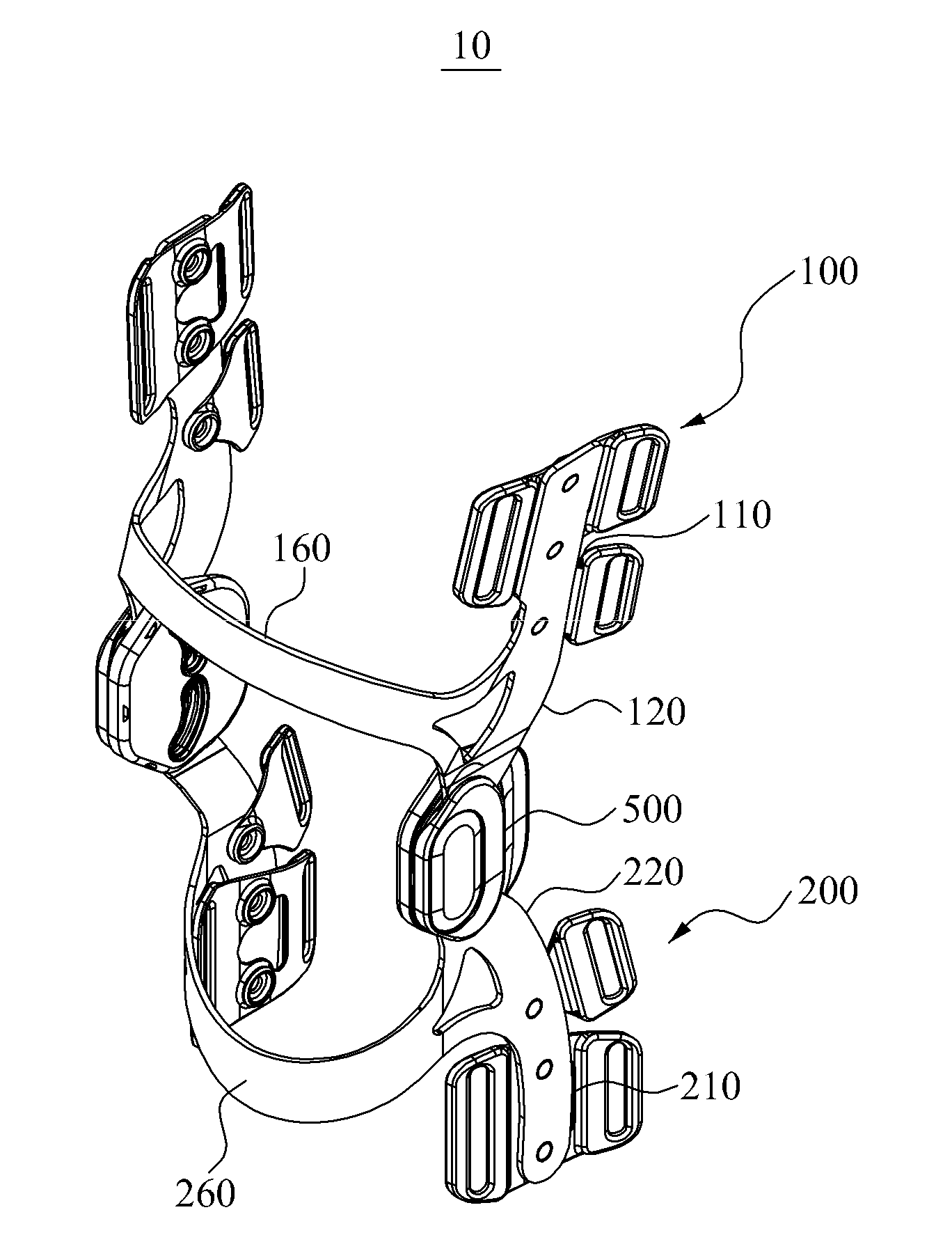
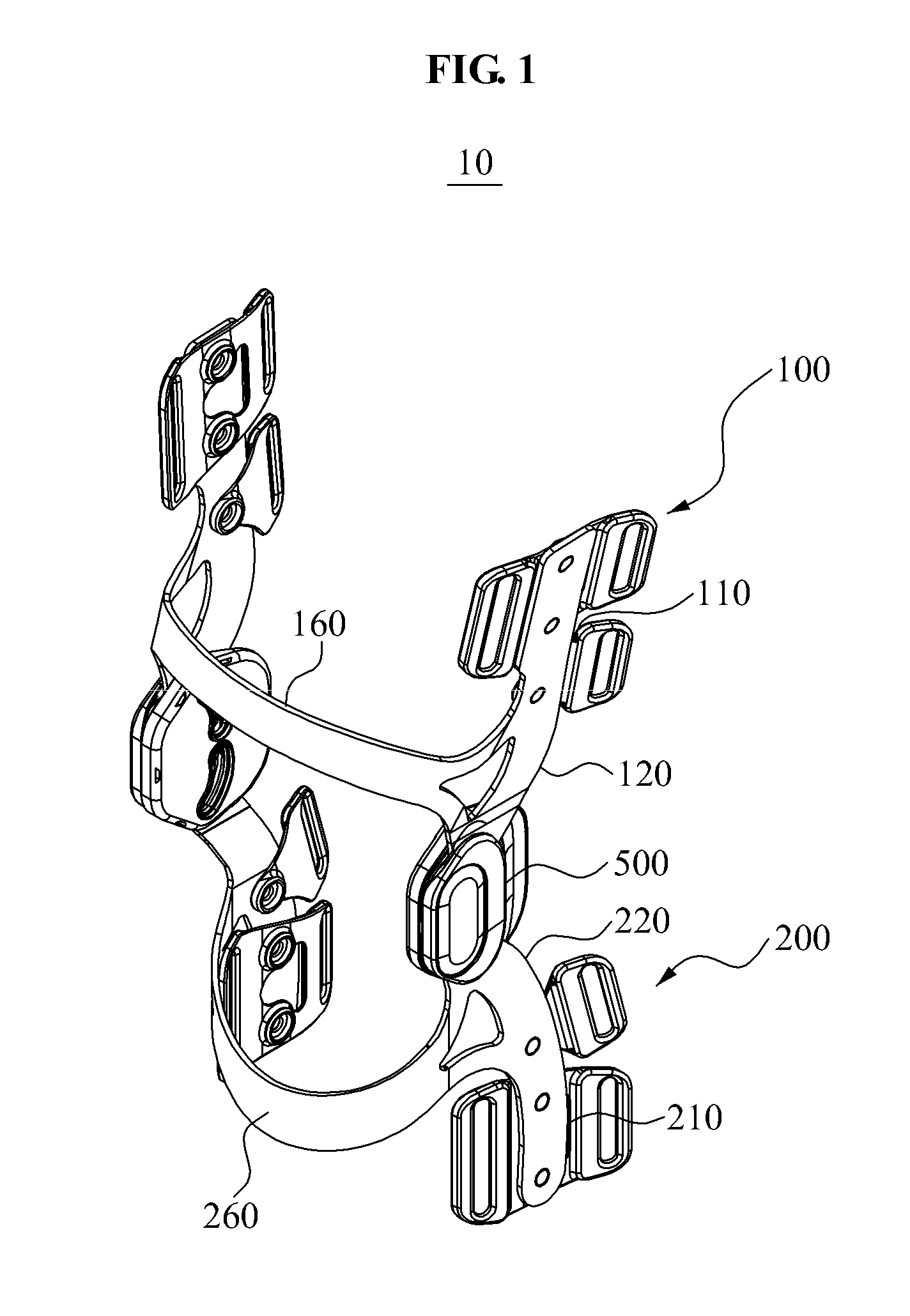
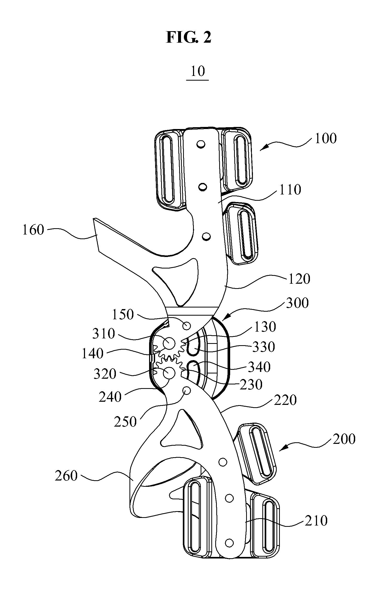
[0054]FIG. 1 is a perspective diagram of a knee traction apparatus 10 according to an embodiment, FIG. 2 illustrates an example in which a cover is removed from the knee traction apparatus 10 and guide grooves have curved shapes, and FIG. 3 illustrates an example in which a cover is removed from the knee traction apparatus 10 and guide grooves have linear shapes. FIGS. 4A through 4C illustrate examples of a stopper installed in the knee traction apparatus 10, FIG. 5 illustrates an example in which a knee joint of a user wearing the knee traction apparatus 10 is straightened, and FIG. 6 illustrates an example in which a knee joint of a user wearing the knee ...


PUM


Abstract

A knee traction apparatus may include an upper frame provided to be worn on a thigh region and including an upper fraction member disposed in an end of the upper frame, and a lower frame provided to be worn on a lower leg region and including a lower traction member that is disposed in an end of the lower frame and is to rotate in mesh with the upper traction member. The upper traction member and the lower traction member may be in contact with each other in front of a knee joint.

Description

CROSS-REFERENCE TO RELATED APPLICATION[0001]This application claims the benefit of Korean Patent Application No. 10-2014-0034837, filed on Mar. 25, 2014, in the Korean Intellectual Property Office, the disclosure of which is incorporated herein by reference.BACKGROUND[0002]1. Field of the Invention[0003]The present invention relates to a knee traction apparatus, and more particularly, to a knee traction apparatus for protecting cartilages by reducing load applied to a knee.[0004]2. Description of the Related Art[0005]A joint refers to a location in which at least two bones forming a skeleton are connected, and all movements of a human body may be performed in joints. Joints enabling the above movements may be referred to as movable joints, and most of skeletons of a human body may be connected by movable joints.[0006]A knee joint among various joints corresponds to a middle portion of a leg, and refers to a hinge joint between a lower end of a femur and an upper end of a tibia.[0007...

Claims


Application Information

Patent Timeline
Patent Type & Authority Applications(United States)
IPC IPC(8): A61F5/01
CPCA61F2005/0139A61F5/0125
Inventor CHANG, KI YONG
Owner CHANGEUI MEDICAL
Why Eureka
Try Eureka