Staple gun

a staple gun and gun body technology, applied in the field of staple guns, can solve the problems of not being able to vary the impact force of any of these previous staple guns, easy deformation of workpieces, and insufficient force being driven into workpieces

Active Publication Date: 2015-10-01
ISABERG RAPID
View PDF2 Cites 6 Cited by
  • Summary
  • Abstract
  • Description
  • Claims
  • Application Information

AI Technical Summary

Problems solved by technology

This means that when a workpiece requiring low force is exposed to the force from a staple gun with a powerfully designed member, the workpiece easily becomes deformed by the impact of the driver against the workpiece, which, if the workpiece is clearly visible, is often perceived as aesthetically objectionable When a staple gun with a weaker member is used for a workpiece that requires high force, it occurs t

Method used


Image

  • Staple gun
  • Staple gun
  • Staple gun

Examples


Embodiment Construction

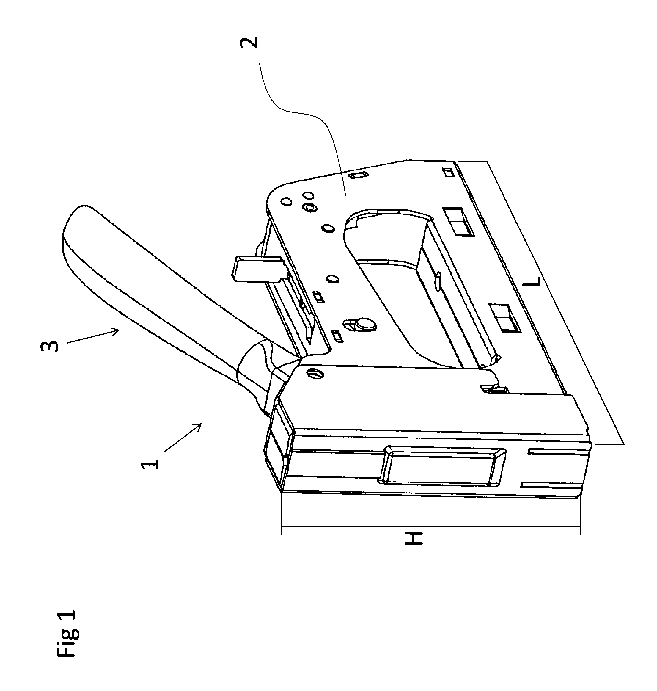
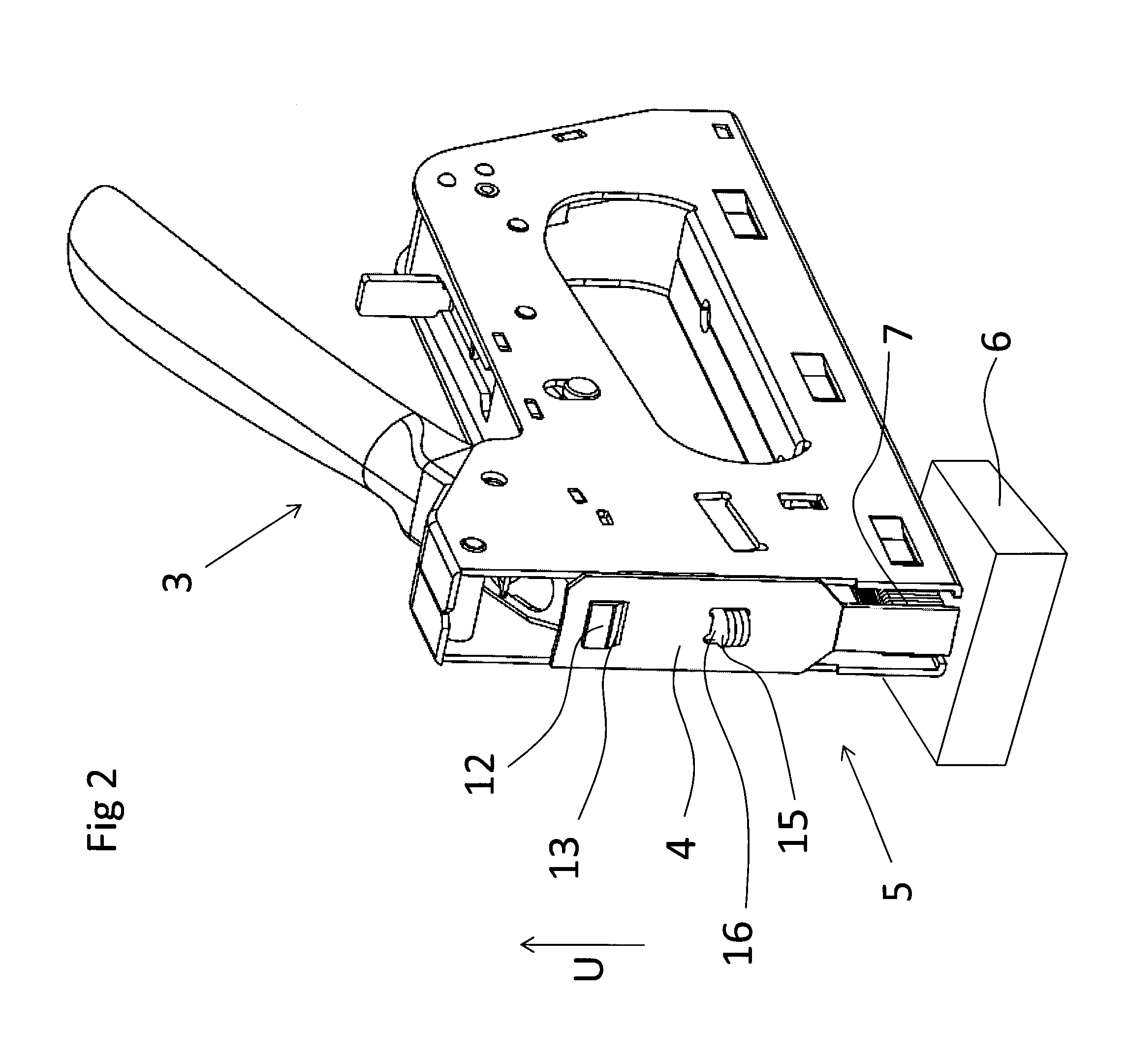
[0018]FIG. 1 shows a staple gun 1, which comprises a frame 2, which has the length L and the height H. Arranged to the frame is an activation member 3, the function of which will be described below. A driver 4 is evident from FIG. 2, which driver is supported in a manner known to the person skilled in the art in a longitudinal edge area 5 of the frame in such a way that it can be conveyed by the activation member in an upward movement U. A workpiece 6 is further evident from the figure as well as staples 7.

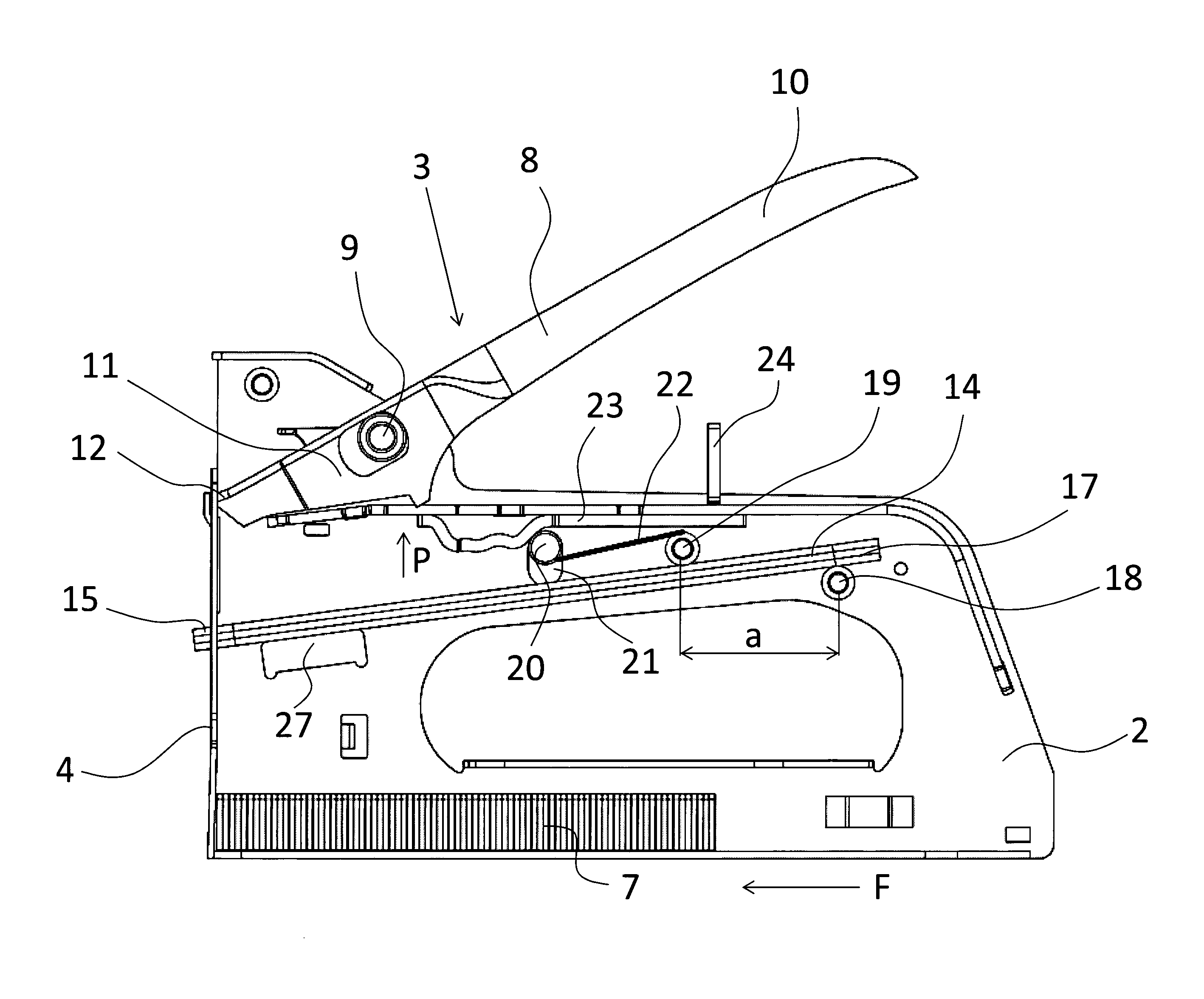
[0019]With reference to FIGS. 2-3, the coupling of the driver 4 to the activation member 3 is evident from them. The activation member comprises a lever arm 8, which is rotatably supported to the frame 2 by a rotary pin 9. The lever arm comprises a long arm 10 and a short arm 11. The short arm 11 comprises a tongue 12, which is inserted into a first opening 13 incorporated in the driver 4. Also apparent from the figures is an elongated elastic member 14, which has the form of a le...


PUM


Abstract

Staple gun for driving staples into a workpiece, which gun includes a frame, arranged in which is a driver, which can be conveyed in an up and downward movement and which in the downward movement (N) executes a drive stroke in which the staple is driven and which can be conveyed by an activation member in the upward movement (U) to a highest height h, in which the activation member releases the driver for the execution of the drive stroke, and which driver is coupled to a first end of an elongated elastic member, which is tensioned when the driver is conveyed in the upward movement for execution of the drive stroke, and which is connected at a second end to a bearing pin assigned to the frame as well as a first breakpoint pin placed between the bearing pin and the driver at a first distance (a) from the bearing pin and around which the elastic member is bent and tensioned when the driver is moved in the upward movement, and a second breakpoint pin placed between the driver and the first breakpoint pin at a second distance (b) from the bearing pin and arranged so that it can be moved between a first position, in which it does not engage with the elastic member when this is moved by the driver in the upward movement, and a second position, in which it engages with the elastic member when the driver is moved in the upward movement and tensions the member, wherein the first distance (a) at which the first breakpoint pin is placed from the bearing pin is related to (h) as 1.6-2.0:1.

Description

TECHNICAL FIELD[0001]The present invention relates to a staple gun for driving staples into a workpiece, which gun comprises a frame, arranged in which is a driver, which can be conveyed in an up and downward movement and which in the downward movement executes a drive stroke, in which a staple is driven, and which by means of an activation member can be conveyed in the upward movement to a highest height, at which the activation member releases the driver for execution of the drive stroke, and which driver is coupled to a first end of an elongated elastic member, which is tensioned when the driver is conveyed in the upward movement for execution of the drive stroke, and which is in engagement at a second end to a bearing pin arranged to the frame as well as a first breakpoint pin placed between the bearing pin and the driver at a first distance from the bearing pin and around which the elastic member is bent and tensioned when the driver is conveyed in the upward movement as well a...

Claims


Application Information

Patent Timeline
IPC IPC(8): B25C5/11
CPCB25C5/11
Inventor EBBESSON, JAN
Owner ISABERG RAPID
Why Eureka
Try Eureka