Toner supplying device and image forming apparatus

Active Publication Date: 2015-10-01
SHARP KK
View PDF5 Cites 3 Cited by
  • Summary
  • Abstract
  • Description
  • Claims
  • Application Information

AI Technical Summary

Benefits of technology

[0008]An object of the present invention is to provide a toner supplying device for supplying toner of a toner cartridge to a developing device, in whi

Problems solved by technology

Moreover, Japanese Laid-Open Patent Publication No. 2012-198368 is for agitating the toner by the agitating member provided in an almost middle part of the intermediate hopper, an

Method used


Image

  • Toner supplying device and image forming apparatus
  • Toner supplying device and image forming apparatus
  • Toner supplying device and image forming apparatus

Examples


embodiment 1

[0052]FIG. 3 is a diagram of the lower part of the storage tank of the toner supplying device when viewed from an axis direction of the conveyance screw.

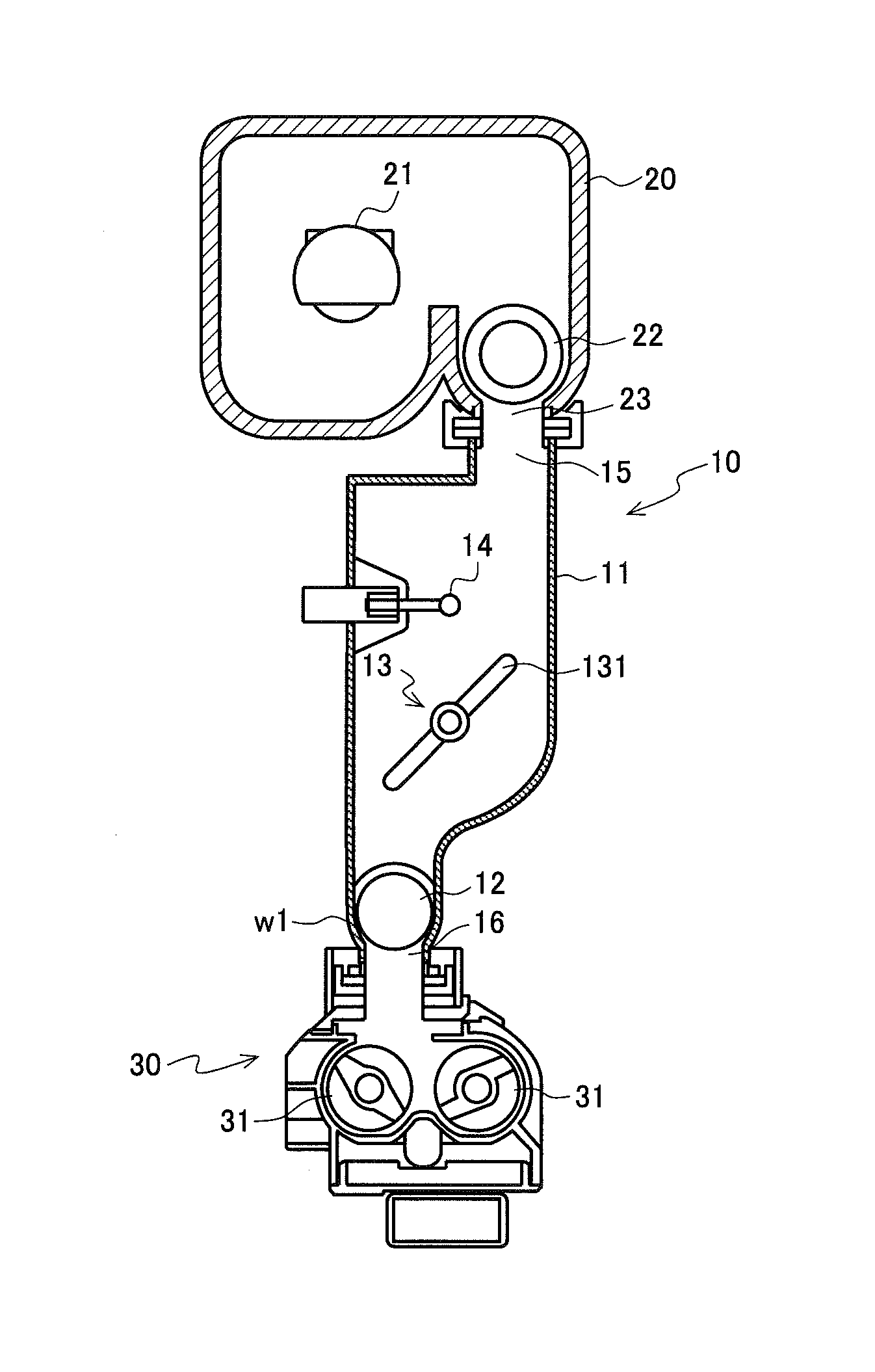
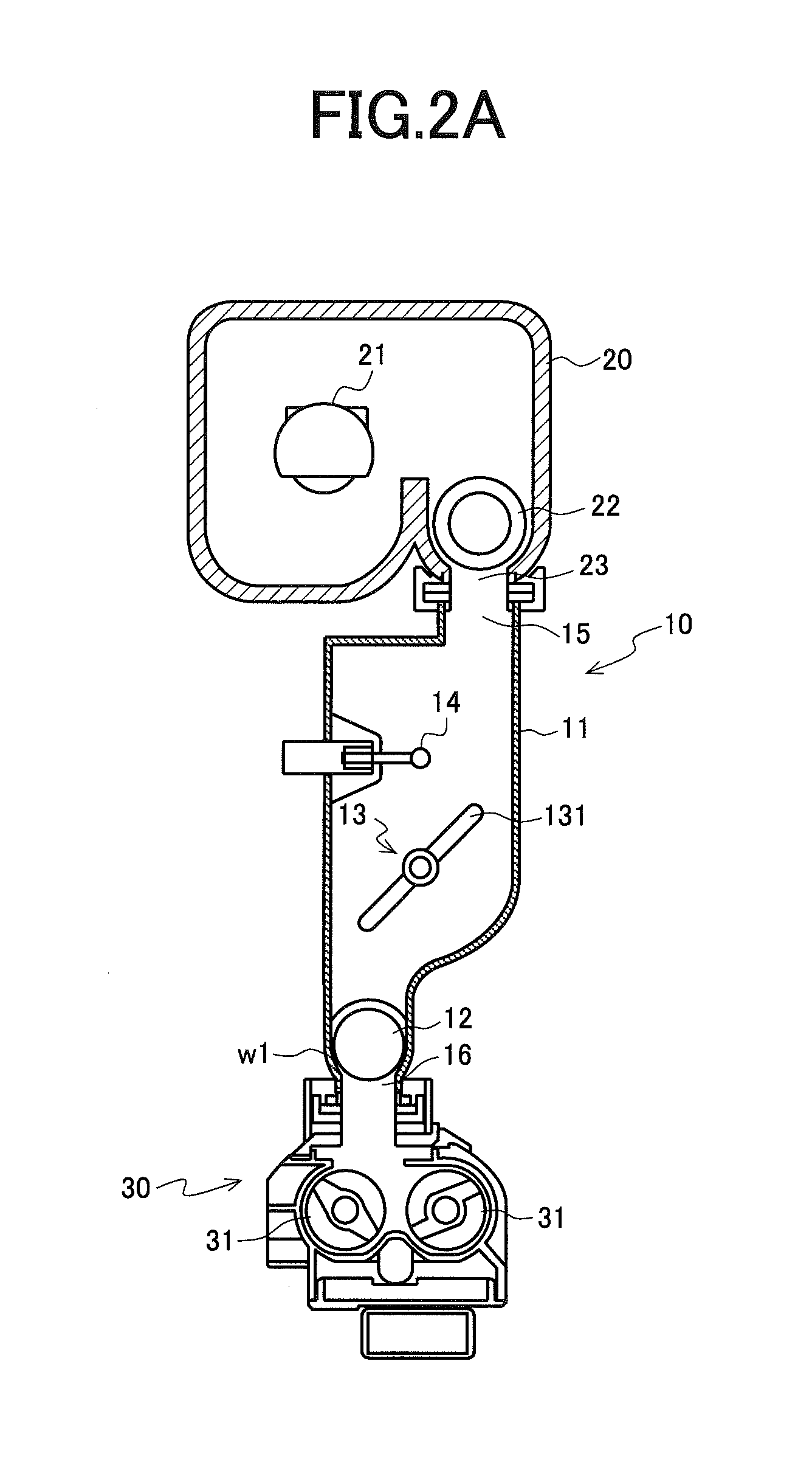
[0053]The storage tank 11 is provided with the conveyance screw 12 for discharging the toner, which is reserved in the storage tank 11 temporarily, to the toner discharge port 16. In this example, the conveyance screw 12 is provided so that the rotational axis coincides with the horizontal direction at the lower part of the storage tank 11.

[0054]The storage tank 11 has bottom part walls w1 having a shape along an outer diameter of the conveyance screw 12 at the lower part of the storage tank 11 and side walls w2 that are connected to the bottom part walls w1 and extend toward an upper part of the storage tank 11 in both sides with an axis of the conveyance screw 12 sandwiched therebetween, and an area P1 where the toner may be packed exists between the bottom part walls w1 and the side walls w2 and the conveyance screw 12.

[0055]In a...

embodiment 2

[0068]In the configuration where the conveyance screw 12 is allowed to be displaced as described above, by further switching a rotational direction of the conveyance screw 12 to forward and reverse for driving, it is possible to prevent packing of toner more effectively.

[0069]FIG. 7 is a diagram explaining an effect of scraping toner in both end parts of the conveyance screw. The conveyance screw 12 is provided so that the rotational axis thereof is coincided with the horizontal direction at the bottom part of the storage tank 11. Here, areas P2 and P3 where the toner may be packed exist in the both end parts of the conveyance screw 12. For example, when the conveyance screw 12 is continued to rotate in a fixed direction, the toner resides in a tip end side thereof and possibility of causing packing is generated.

[0070]Therefore, in the present embodiment, by switching the rotational direction of the conveyance screw 12 to forward and reverse for driving, packing of the toner is prev...

embodiment 3

[0078]In the present embodiment, by optimizing an angle of a wall surface around the conveyance screw 12 that is disposed in the lower part of the storage tank 11 of the toner supplying device 10, packing of toner is suppressed effectively. FIG. 9 is a diagram explaining an exemplary configuration of a wall part around the conveyance screw in the storage tank.

[0079]In the same manner as each embodiment described above, the toner supplying device 10 of the present embodiment has the storage tank 11 in which toner supplied from the toner cartridge is temporarily stored and discharges the toner from the toner discharge port 16 provided in a lower end of the storage tank 11. The storage tank 11 is provided with the conveyance screw 12 for discharging the toner which is stored in the storage tank 11 temporarily to the toner discharge port 16. The conveyance screw 12 is provided so that the rotational axis thereof is coincided with the horizontal direction at the lower part of the storage...


PUM


Abstract

It is enabled to prevent packing of toner and supply toner stably. A toner supplying device has a toner cartridge attached to an upper part thereof a storage tank in which toner supplied from the toner cartridge is stored temporarily and discharges the toner from a toner discharge port provided in a lower end of the storage tank. A conveyance screw for discharging the toner from the toner discharge port is provided inside the storage tank and the storage tank has a shaft support hole for supporting a shaft of the conveyance screw that coincides with a rotational center axis of the conveyance screw. The shaft support hole is formed as along hole in which the shaft is able to be displaced in one direction or a direction opposite to the one direction.

Description

CROSS-NOTING PARAGRAPH[0001]This non-provisional application claims priority under 35 U.S.C. §119(a) on Patent Application No. 2014-071653 filed in JAPAN on Mar. 31, 2014, the entire contents of which are hereby incorporated herein by reference.FIELD OF THE INVENTION[0002]The present invention relates to a toner supplying device and an image forming apparatus, and more specifically relates to a toner supplying device that has a storage tank in which toner supplied from a toner cartridge is temporarily stored and discharges the toner from a toner discharge port provided in a lower end of the storage tank to supply to a developing device, and an image forming apparatus provided with the toner supplying device.BACKGROUND OF THE INVENTION[0003]Electrophotographic image forming apparatuses such as a copier, a printer and a facsimile have been known. These image forming apparatuses form an electrostatic latent image on a surface of a photoreceptor, develop this electrostatic latent image ...

Claims


Application Information

Patent Timeline
IPC IPC(8): G03G15/08
CPCG03G15/0891G03G15/0877
Inventor MAEHARA, HIROYOSHI
Owner SHARP KK
Why Eureka
Try Eureka