Compression heel prosthetic foot

a prosthetic foot and compression heel technology, applied in the field of prosthetic feet, can solve the problems of increasing the risk of injury to an amputee using the foot, creating instability for users, and forcing a constant imbalance or rebalance of postur

Inactive Publication Date: 2015-10-08
PROTEOR USA LLC
View PDF11 Cites 4 Cited by
  • Summary
  • Abstract
  • Description
  • Claims
  • Application Information

AI Technical Summary

Problems solved by technology

In use, such prosthetic feet typically do not replicate the action of a real foot and can generate “kickback” or “kickforward” reactions that increase the risk of injury to an amputee utilizing the foot.
Either motion may create instability for user if expanding or restricting the intended motion.
Further, many prior art prosthetic foot generate vibrations that can travel through a user's leg and cause discomfort.
For an amputee, loosing bipedality may produce an involuntary anterior lean or shift, forcing a constant imbalance or rebalance of posture.

Method used


Image

  • Compression heel prosthetic foot
  • Compression heel prosthetic foot
  • Compression heel prosthetic foot

Examples


Embodiment Construction

[0015]While exemplary embodiments are described herein in sufficient detail to enable those skilled in the art to practice the invention, it should be understood that other embodiments may be realized and that logical structural, material, and mechanical changes may be made without departing from the spirit and scope of the invention. Thus, the following descriptions are not intended as a limitation on the use or applicability of the invention, but instead, are provided merely to enable a full and complete description of exemplary embodiments.

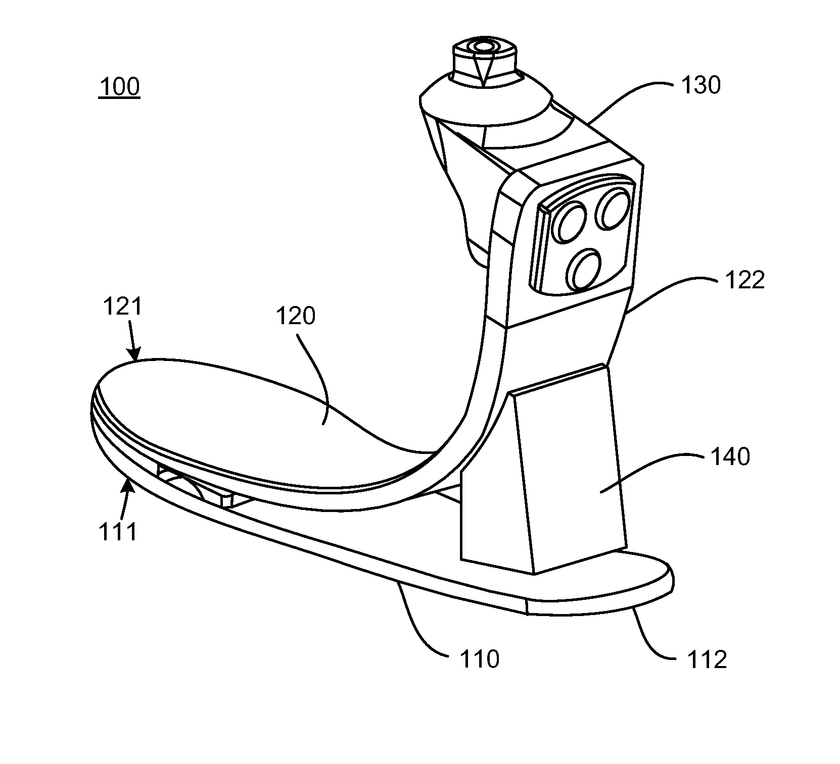
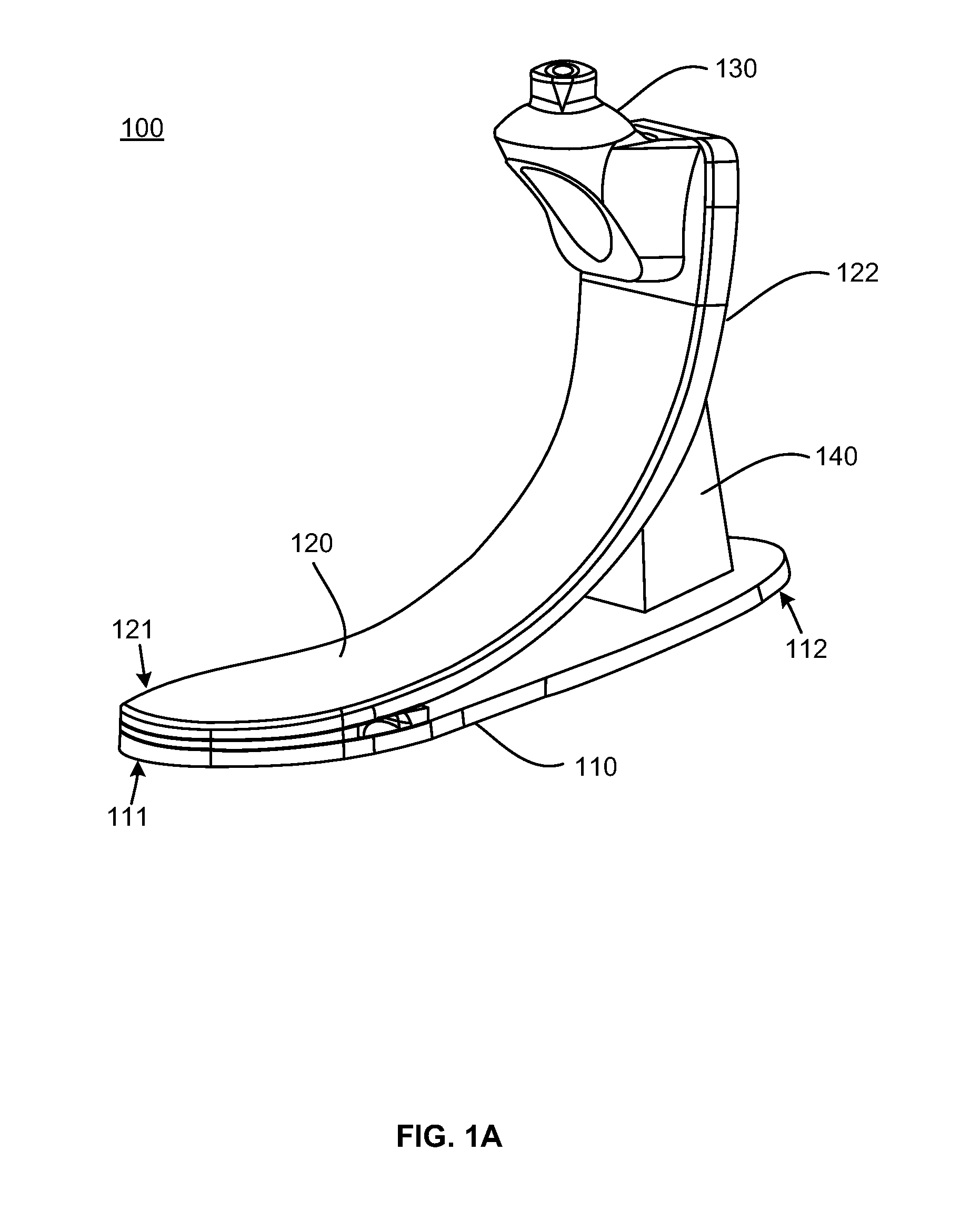
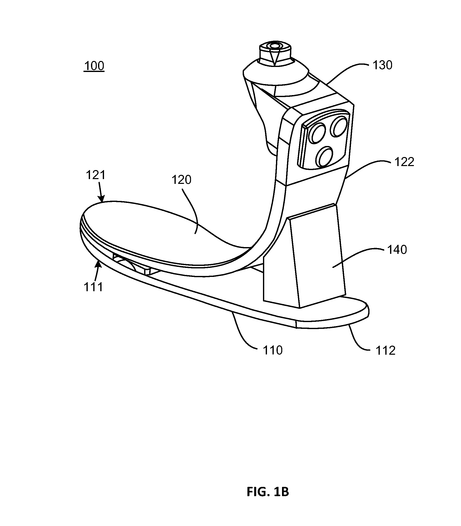
[0016]Briefly, in accordance with exemplary embodiments, a prosthetic foot has improvements over a prior art prosthetic foot in that a more natural motion and response of the foot occurs during movement. In particular, the movement of the exemplary prosthetic foot replicates the natural flex of a foot and supplies continuous energy to a person when striding from heel to toe.

[0017]In the exemplary embodiment a prosthetic foot stores energy durin...


PUM


Abstract

A prosthetic foot comprises a resilient bottom member, a resilient top member, wherein the anterior top end is connected to the anterior bottom end of the resilient bottom member, and wherein the resilient top member is positioned over the resilient bottom member, and an elastomeric bumper member comprising a tapered surface configured to contact the resilient bottom member and attached to an underside of the posterior of the resilient top member. The prosthetic foot can further comprise a toe pad having a spacer coupled to, and creating space between, the bottom member and the top member, and an adhesive bonding one of the bottom member and one end of the top member, where the adhesive is commingled with the spacer between the first bottom end and the first top end.

Description

CROSS-REFERENCES TO RELATED APPLICATIONS[0001]This application is a continuation of U.S. patent application Ser. No. 13 / 568,535, filed on Aug. 7, 2012; and this application is a continuation of U.S. patent application Ser. No. 13 / 568,535, filed on Aug. 7, 2012, which is a continuation-in-part of International Application No. PCT / US11 / 33319, filed on Apr. 20, 2011, which is a continuation-in-part of U.S. patent application Ser. No. 12 / 799,215, filed on Apr. 20, 2010, which is a continuation-in-part of U.S. patent application Ser. No. 11 / 901,845, filed on Sep. 19, 2007, now U.S. Pat. No. 8,048,173; and this application is a continuation-in-part of U.S. patent application Ser. No. 13 / 642,501, filed on Nov. 27, 2012, which is a 371 national phase application of International Application No. PCT / US11 / 33319, filed on Apr. 20, 2011, which is a continuation-in-part of U.S. patent application Ser. No. 12 / 799,215, filed on Apr. 20, 2010, which is a continuation-in-part of U.S. patent applicat...

Claims


Application Information

Patent Timeline
Patent Type & Authority Applications(United States)
IPC IPC(8): A61F2/66
CPCA61F2/66A61F2002/6642A61F2002/6614A61F2002/5009A61F2002/6664
Inventor SMITH, KEITH B.PARKER, GENE
Owner PROTEOR USA LLC
Why Eureka
Try Eureka