Cabled backplane system having an electromagnetic radiation absorber

a backplane system and electromagnetic radiation technology, applied in the field of communication systems, can solve the problems of difficult to achieve a baseline level of signal integrity, electrical connector systems that operate with data transmission rates above 10 gbps (gigabits/second) are often vulnerable to electromagnetic interference (emi), and achieve the effect of suppressing the propagation of electromagnetic radiation

Active Publication Date: 2015-08-18
TYCO ELECTRONICS LOGISTICS AG (CH)
View PDF9 Cites 5 Cited by
  • Summary
  • Abstract
  • Description
  • Claims
  • Application Information

AI Technical Summary

Benefits of technology

[0006]In an embodiment a cable backplane system is disclosed. The cable backplane system has a backplane having a plurality of backplane openings therethrough. The backplane has mounting areas surrounding corresponding openings. The cable backplane system includes a cable rack coupled to a rear of the backplane. The cable rack comprises a tray having a frame with side walls surrounding a cavity defining a raceway. The side walls extend from a front edge of the frame. The cable rack also includes spacers coupled to the tray proximate to the front edge. The cable connectors have cables extending therefrom and routed in the raceway. The cable connectors are received in corresponding backplane openings and held in position relative to the backplane by the spacers. The cable rack also includes an electromagnetic radiation (EMR) absorber extending along the front edge of the frame. The EMR absorber engages corresponding mounting areas of the backplane. The EMR absorber suppresses the propagation of electromagnetic radiation into or out of the tray.
[0007]In an embodiment, a cable backplane system is disclosed. The cable backplane system comprises a tray having a frame with side walls surrounding a cavity defining a raceway. The side walls extend to a front edge of the frame. The tray includes a bottom having an opening provided along the bottom of the tray. The tray also includes a top having an opening provided along the top of the tray. The cable backplane system also includes spacers coupled to the tray proximate to the front edge. The cable backplane system also includes cable connectors having a plurality of cables extending therefrom and routed in the raceway. The cable connectors are held in position relative to the backplane by the spacers. The cable backplane system also includes electromagnetic radiation absorbers extending along at least one of the top opening and the bottom opening in the tray to suppress the propagation of electromagnetic radiation into or out of the tray.

Problems solved by technology

As the density of the systems increase and as the requirements for high speed lines become more complex, achieving a baseline level of signal integrity can be challenging.
Electrical connector systems that operate with data transmission rates above 10 Gbps (Gigabits / second) are often vulnerable to electromagnetic interference (EMI).
However, in order to perform maintenance on an individual tray, all of the trays in the chassis have to be powered down.

Method used


Image

  • Cabled backplane system having an electromagnetic radiation absorber
  • Cabled backplane system having an electromagnetic radiation absorber
  • Cabled backplane system having an electromagnetic radiation absorber

Examples


Embodiment Construction

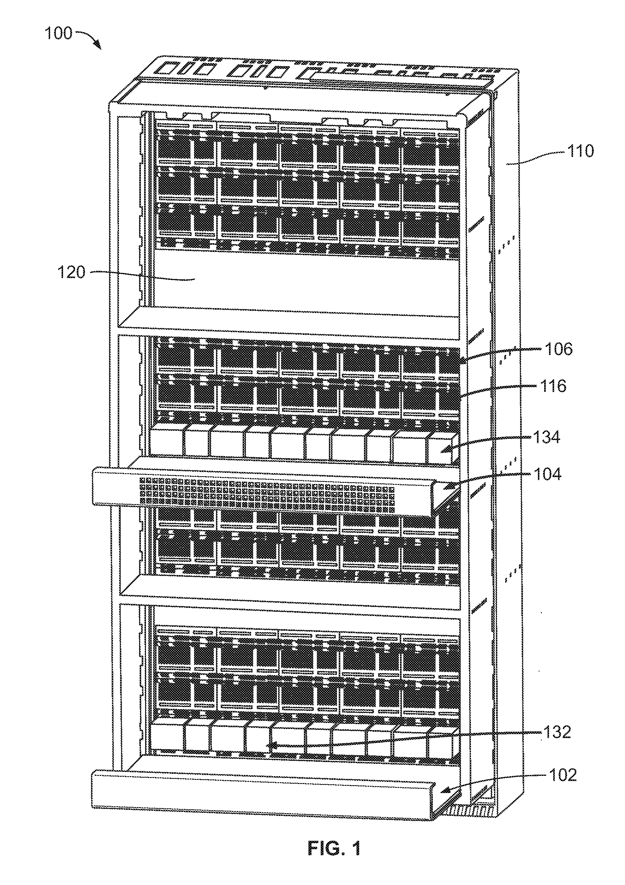
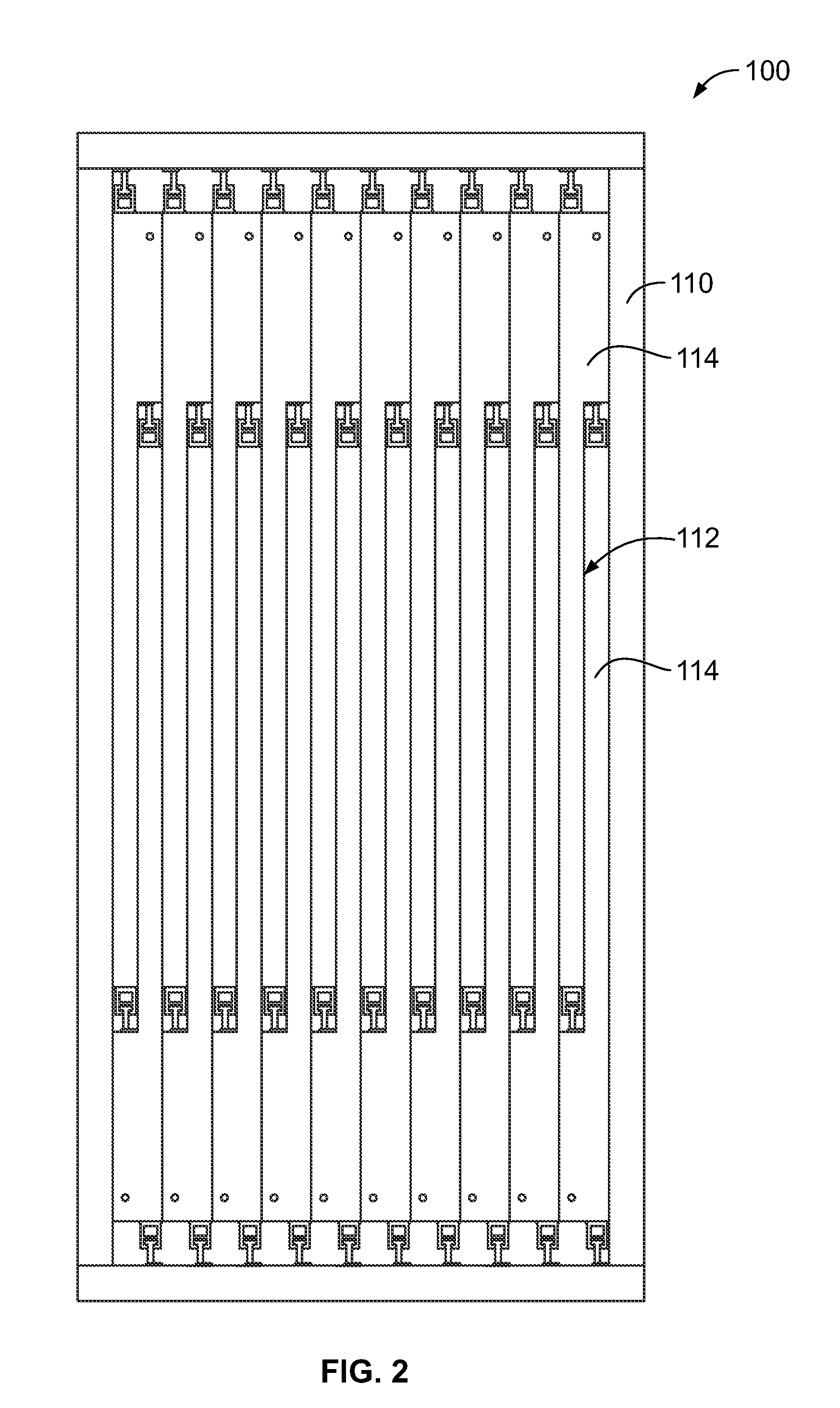
[0015]FIG. 1 is a front perspective view of a cable backplane system 100 formed in accordance with an exemplary embodiment. FIG. 2 is a rear perspective view of the cable backplane system 100. The cable backplane system 100 is used in a data communication application, such as a network switch. The cable backplane system 100 interconnects line cards 102 and switch cards 104 using cable connector assemblies 106. The cable backplane system 100 may be used to interconnect with other types of connectors and / or cards, such as daughtercards, in other embodiments.

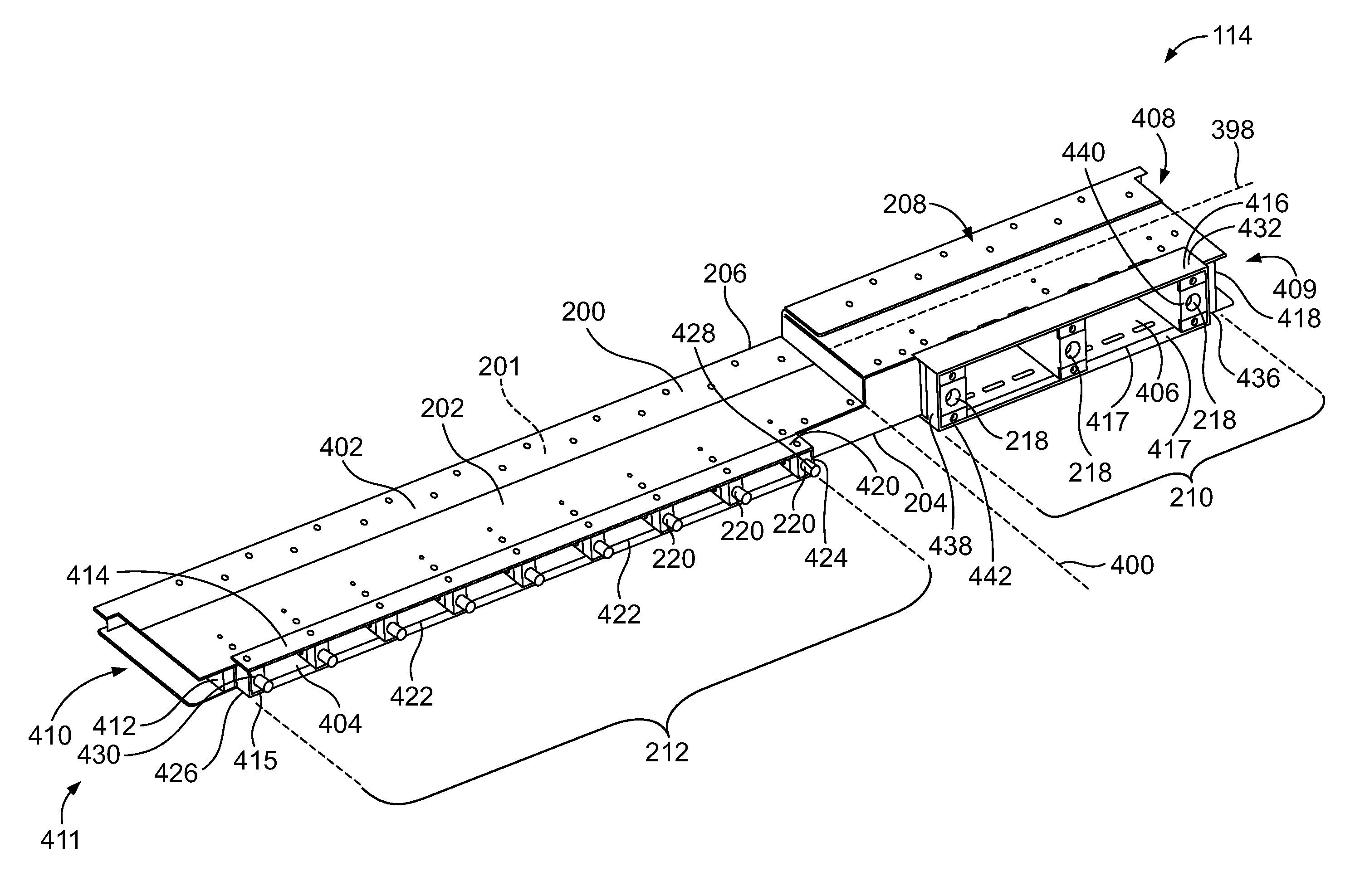
[0016]The cable connector assemblies 106 include cable connectors 116 that are interconnected by cables within the cable backplane system 100. The cable connector assemblies 106 eliminate interconnections via traces of a circuit board, such as a backplane circuit board. The cable connector assemblies 106 have improved signal performance along the signal paths between various connectors of the cable backplane system 100 as compared ...


PUM


Abstract

A cable backplane system includes a tray having a frame with side walls surrounding a raceway. The side walls extend to a front edge of the frame. The tray includes spacers coupled to the tray located proximate to the front edge. Cable connectors are held by corresponding spacers in position relative to the backplane. The cable backplane system includes an electromagnetic radiation (EMR) absorber extending along an opening in the tray to suppress the propagation of EMR into or out of the tray.

Description

BACKGROUND[0001]The subject matter herein relates generally to communication systems that utilize cable connectors.[0002]Communication systems, such as network systems, servers, data centers, and the like, use large printed circuit boards, known as backplanes, to interconnect midplanes, daughtercards, line cards and / or switch cards. The communication systems use high speed differential connectors mounted to the backplane and high speed differential connectors mounted to the line cards and switch cards to transmit signals therebetween. The backplane interconnects the various connectors using traces along the circuit board.[0003]As the density of the systems increase and as the requirements for high speed lines become more complex, achieving a baseline level of signal integrity can be challenging. At least some systems have replaced the traditional backplanes with cabled backplane systems. In cabled backplane systems, cable connectors of a tray directly engage mating connectors of lin...

Claims


Application Information

Patent Timeline
Patent Type & Authority Patents(United States)
IPC IPC(8): H01R13/648H05K7/14
CPCH05K7/1451H01R13/648H01R13/6598H04Q1/116
Inventor ROSSMAN, JARED EVAN
Owner TYCO ELECTRONICS LOGISTICS AG (CH)
Why Eureka
Try Eureka