Eureka AIR delivers breakthrough ideas for toughest innovation challenges, trusted by R&D personnel around the world.

Stabilized load tray

Inactive Publication Date: 2015-10-08
DOW GLOBAL TECH LLC
View PDF12 Cites 4 Cited by
  • Summary
  • Abstract
  • Description
  • Claims
  • Application Information

AI Technical Summary

Benefits of technology

The invention is a stabilized load tray that can support a load stack. It has a horizontal floor, vertical side walls, and a top connected to the side walls. It also has a deployable lip that can be folded from a substantially horizontal position to a substantially vertical position adjacent to the load stack. The tray can be made from a composition comprising at least one polymer. The tray has a uniform thickness and the outer height and width of the pillar can vary depending on the needs of the user. The tray can also have at least two bolsters located at opposite side walls. The technical effects of the invention include improved stability, load capacity, and flexibility for the user.

Problems solved by technology

First, without modifications, traditional pallets offer very little lateral support for stacked loads.
For loads that include flexible or semi-rigid containers, the lack of lateral support can cause the load to slump, fall or slide from the pallet.
Second, traditional pallet designs require the use of forklifts to raise, lower and move the palleted load.
In many locations, the absence of a trailer-high loading dock frustrates the ability to position a forklift or truck adjacent a pallet located within the interior of a trailer.
Traditional pallets are not designed to withstand the stress, abrasion, uneven twisting torque and jerking of being pulled along the floor of a trailer by a chain.
When moved in this manner, traditional pallets often fail, causing the stacked load to fall.

Method used


Image

  • Stabilized load tray
  • Stabilized load tray
  • Stabilized load tray

Examples


Embodiment Construction

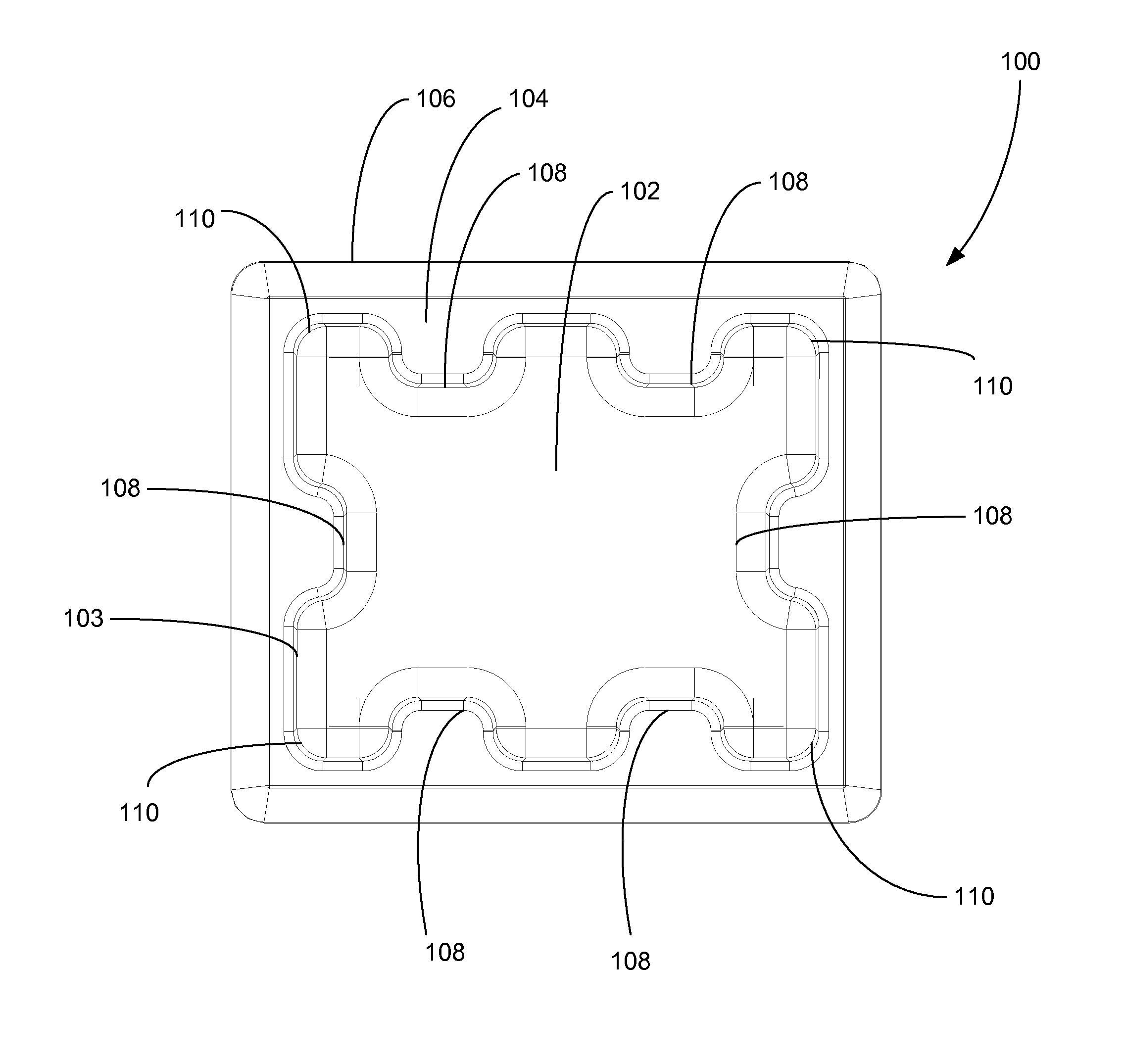
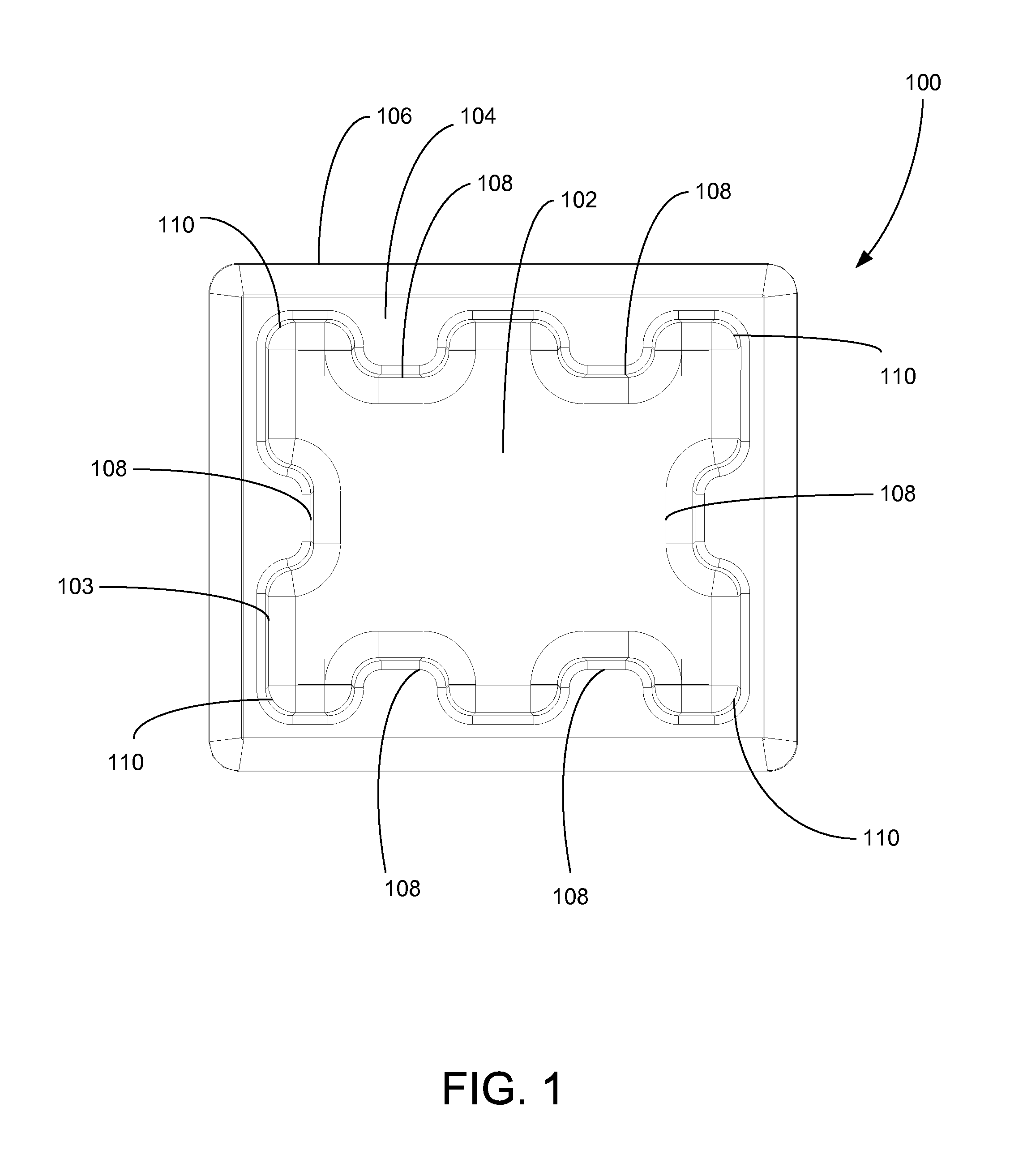
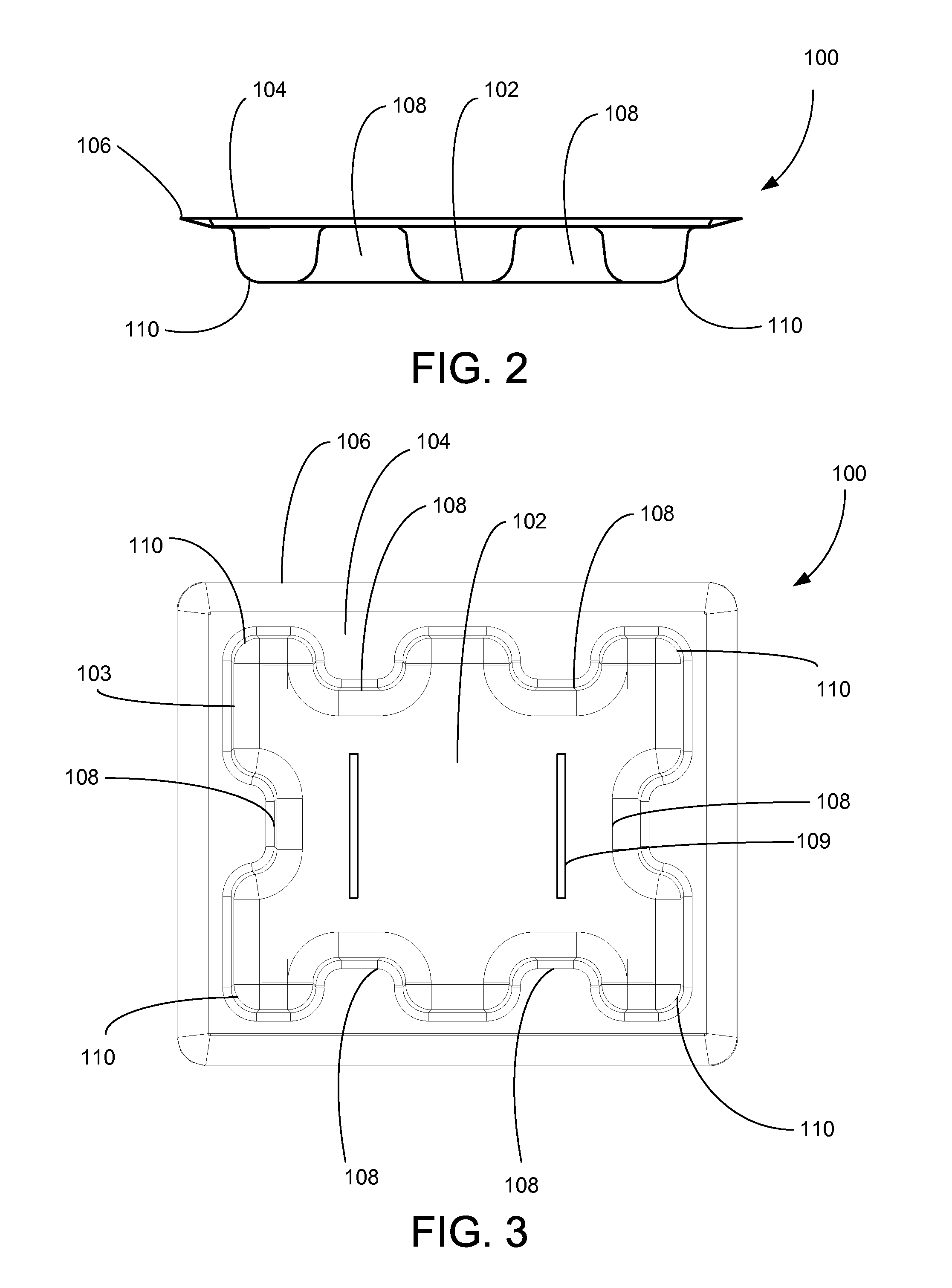
[0008]An inventive stabilized load tray may comprise two or more embodiments, as described herein.

[0009]The invention provides a stabilized load tray for supporting a load stack, the stabilized load tray comprising:[0010]a horizontal floor;[0011]vertical side walls connected to the floor;[0012]a top connected to the side walls; and[0013]a deployable lip connected to the top, wherein the deployable lip can be folded from a substantially horizontal position to a substantially vertical position adjacent the load stack.

[0014]In one embodiment, the stabilized load tray comprises a plurality of bolsters extending from the side walls.

[0015]In one embodiment, the deployable lip comprises a unitary lip that extends around the periphery of the top of the stabilized load tray. In another embodiment, the deployable lip comprises a series of independent rails connected to the top of the stabilized load tray.

[0016]In one embodiment, the inner length of the tray (ILT) is greater than, or equal to,...


PUM


Abstract

The invention provides a stabilized load tray for supporting a load stack, the stabilized load tray comprising:a horizontal floor;vertical side walls connected to the floor;a top connected to the side walls; anda deployable lip connected to the top, wherein the deployable lip can be folded from a substantially horizontal position to a substantially vertical position adjacent the load stack.

Description

REFERENCE TO RELATED APPLICATIONS[0001]This application claims the benefit of U.S. Provisional Patent Application 61 / 718,619, filed Oct. 25, 2012, and U.S. Provisional Patent Application 61 / 890,666, filed Oct. 14, 2013, both of which are incorporated herein by reference.FIELD OF THE INVENTION[0002]The present invention relates generally to the improvement of load-handling trays. More particularly, the present invention relates to a functionally improved and more economical load-handling tray.BACKGROUND OF THE INVENTION[0003]Materials handling pallets and trays are commonly used to transport a wide variety of products in bulk quantities. Pallets are typically rectangular-shaped boxes that are configured to support loads without significant deformation or structural failure. Although many pallets are constructed from wood, plastic pallets are becoming increasingly popular. Plastic pallets can support heavier loads, are impervious to rot and infestation and are less flammable than conv...

Claims


Application Information

Patent Timeline
IPC IPC(8): B65D1/34
CPCB65D1/34B65D19/0034B65D19/0036B65D19/0038B65D2519/00034B65D2519/00069B65D2519/00268B65D2519/00288B65D2519/00323B65D2519/00333B65D2519/00343B65D2519/00348B65D2519/00412B65D2519/00815B65D2519/0087B65D2519/0094B65D2571/00018B65D71/0096
Inventor LINDLEY, DAVIDBELLEFONTAINE, WILLIAM B.
Owner DOW GLOBAL TECH LLC
Why Eureka
Eureka Blog
Learn More