Inflatable structure

Inactive Publication Date: 2015-10-22
NEIL PRYDE LTD
6 Cites 9 Cited by

AI-Extracted Technical Summary

Problems solved by technology

These disclosures are directed at products with increased strength and stiffness, but suffer ...

Method used

[0048]In some embodiments the second chamber 3 provides the non shape-forming or non-structural elements of the envelope 1. In such embodiments the second chamber 3 is inflated to a pressure lower than the shape-forming tubes 2, but higher than atmospheric pressure although this is not essential to the invention and the second chamber 3 may be at atmospheric pressure. In order to prevent the upper and lower walls 4, 5 from bulging and to give shape to the upper and lowers walls 4, 5 and envelope 1, the secondary chamber 3 includes one or more, preferably a plurality of, secondary shape-forming members 6 joined between the upper wall 4 and the lower wall 5. The secondary shape-forming members 6 prevent the upper and lower walls 4, 5 from bulging apart under pressure by defining a maximum distance between the upper and lower walls 4, 5. In the preferred embodiment the secondary shape-forming members 6 extending longitudinally and/or transversely within the second chamber 3 of the envelope 1 to define different maximum distances between the upper wall 4 and the lower wall 5 at two or more positions spaced apart longitudinally and/or transversely. Defining different maximum distances between the upper and lower walls 4, 5 provides shape to the envelope 1 such that the upper wall 4 and lower wall 5 are not parallel in a respective longitudinal or transverse direction. This can be used for example to provide rocker between the nose 7 and tail 8 of a paddleboard, as illustrated in FIG. 13, and also to reduce the thickness of the board laterally towards its side edges 9 and longitudinally towards its front 7. The secondary shape-forming members 6 can be one or more threads joining the upper wall 4 and the lower wall 5, or can be one or more ribs joining the upper wall 4 and the lower wall 5. In some embodiments the ribs are cross, or X-ribs and illustrates in FIGS. 3, 4, 7 and 8, or planer vertical I-ribs as illustrated in FIG. 9. In some embodiments the ribs form spaces or chambers 3 into which inflatable bladders are inserted. In other embodiments the ribs themselves are one or more second airtight shape-forming tubes 30, of the same of similar type to the pre-shaped inflatable tubes 50, attached directly to and between the upper wall 4 and lower wall 5 using suitable glue 31. The inflatable bladders inserted into spaces formed by ribs, or alternately the airtight shape-forming tubes 30, can be inflated to a third pressure higher than the second pressure and equal or lower than the first pressure. Also, in the preferred embodiment a plurality of ...

Benefits of technology

[0014]Preferably, the secondary shape-forming member(s) is/are one or more threats joint the upper wall and the lower wall.
[0015]Preferably, the secondary shape-forming member(s) is/are one or more ribs joint the upper wall and the lower wall and extending through the envelope to d...

Abstract

An inflatable structure and in particular, although not exclusively, a device such as an inflatable water craft, a kite or a shelter. Also an inflatable tube for an inflatable structure.

Application Domain

UmbrellasWater sport boards +9

Technology Topic

Engineering

Image

  • Inflatable structure
  • Inflatable structure
  • Inflatable structure

Examples

  • Experimental program(1)

Example

[0044]The following description is given by way of example only to illustrate the invention. It is not intended to limit the scope of use or functionality of the invention. In particular, the invention is not limited in its application to the details of construction and the arrangements of components set forth in the following description or illustrated in the accompanying drawings. The invention is capable of other embodiments and of being practiced or being carried out in various ways. Also, it is to be understood that the phraseology and terminology used is for the purpose of description and should not be regarded as limiting.
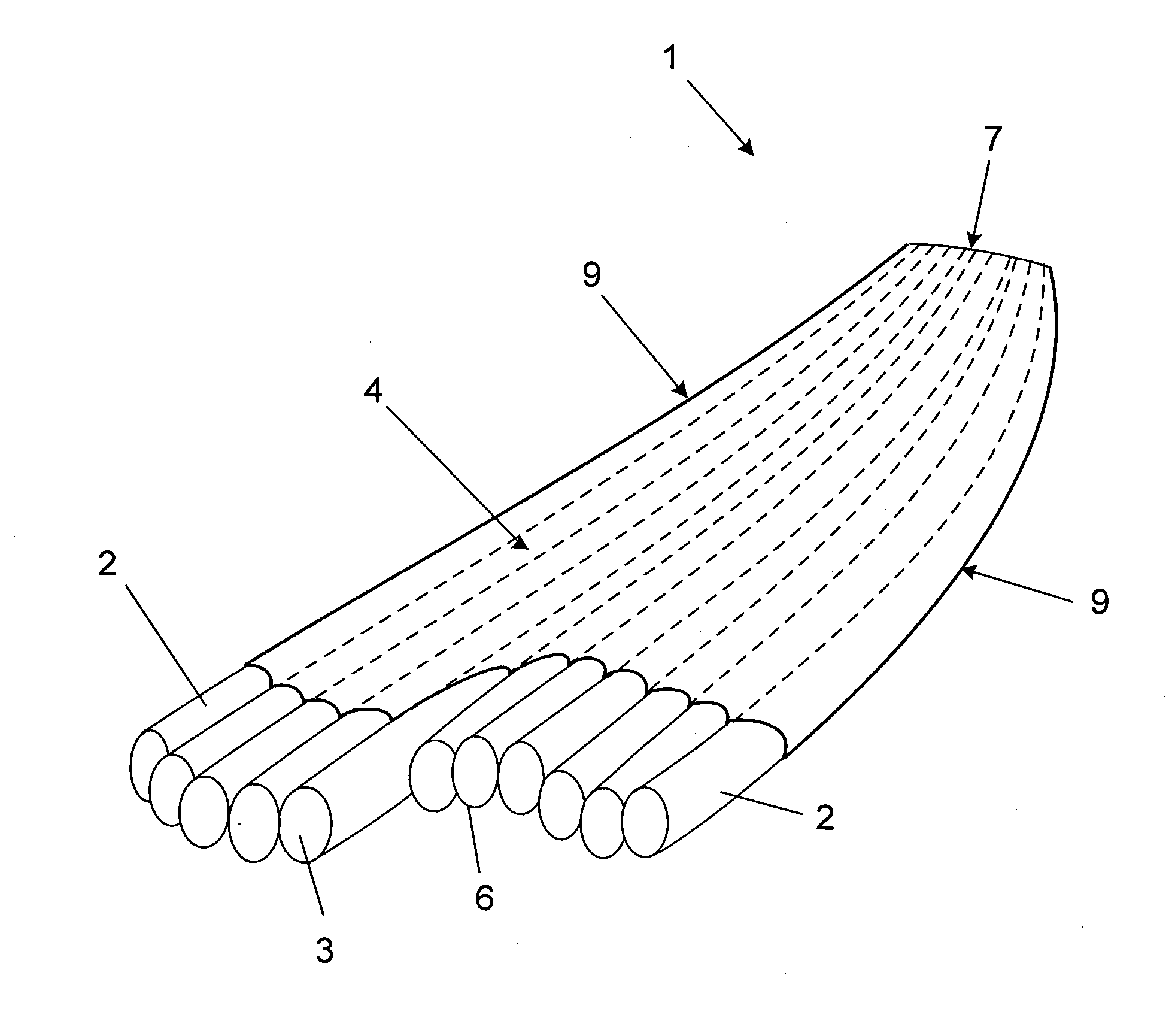
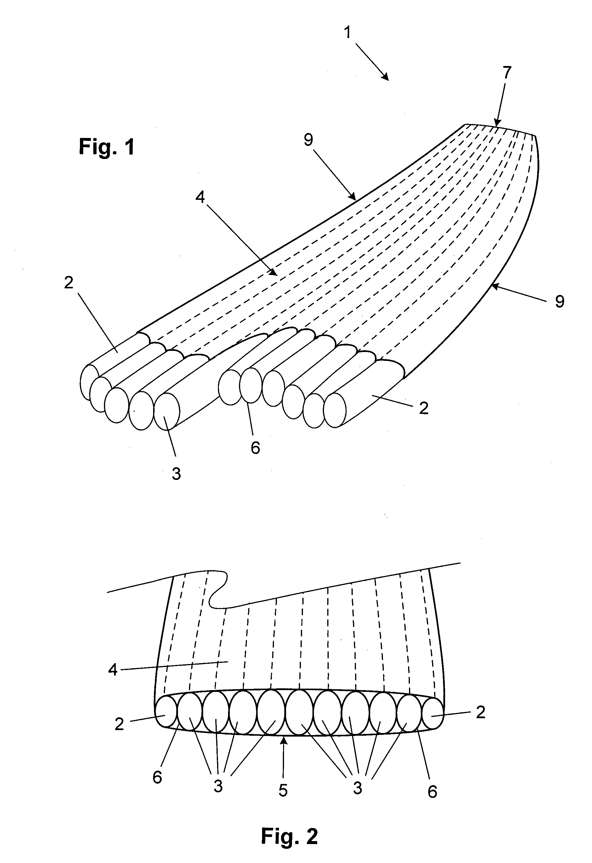
[0045]In one embodiment the invention provides for an inflatable structure suitable for use in numerous products including but not limited to water craft such as kayaks or canoes, surfboards, surf skis and paddle boards such as a stand-up paddle boards (SUPs), inflatable wings, sports kites such as those used in Kiteboarding, shelters such as tents and awnings, non-rigid containers such as bags, backpacks or bike bags, aircraft rescue slides and inflatable advertising signs. For the purpose of illustrating the invention the drawings show the invention applied to a stand-up paddle board (SUP), however, this is not intended to limit the scope of use or functionality of the invention which may be applied to any inflatable structure comprising an envelope. One embodiment of the invention discussed herein provides a pre-shaped inflatable structure having one or more pre-shaped inflatable tubes. The pre-shaped tubes may be inflated with bladders, or alternatively may be bladderless. In some embodiments the bladders used to inflate the pre-shaped tubes may themselves be pre-shaped tubes.
[0046]An inflatable structure according to the invention comprises an envelope 1 which forms the main body of the structure. In the illustrated embodiment, of FIG. 1 for example, the envelope 1 has a front or nose end 7, a back or tail end 8 and two elongate sides 9 joint between the nose 7 and tail 8. Such an envelope is suitable for use as a stand-up paddle board (SUP). The envelope 1 is formed from a plurality of pre-shaped chambers 2, 3 of which at least one chamber 2 is inflated to a pressure higher than atmospheric pressure to provide a shape-forming support structure for the envelope 1. In one embodiment the shape-forming chamber 2 is a pre-shaped inflatable tube 50 (see FIG. 10) made from a plurality of flexible stretch resistant threads or fibres that are bonded together by an elastic plastic such as thermoplastic polyurethane (TPU). Such a pre-shaped tube 50 can be made, for example, buy applying a woven tubular sock 53 to a shape-forming member having a desired tapered and/or a curvilinear shape. The sock 53 is deformed to the shape of the shape-forming member and an elastic thermoplastic 51, 52 is applied to the woven sock 53 to bond together the threads or fibres of the sock. The elastic thermoplastic 51, 52 locks the fibres or threads of the sock 53 to the shape of the forming member such that when the inflatable tube is inflated it takes on the desired shape. The elastic thermoplastic also provides the tube with airtight qualities such that, in a preferred embodiment of the invention, the pre-shaped inflatable tube is bladderless. The envelope 1 also has at least one second chamber 3 that is inflated to a pressure lower than the airtight shape-forming chamber 2. The shape-forming chamber 2 at least partially surrounds the second chamber 3, preferable defining a structural edge of the envelope 1. The second chamber 3 is preferably formed by fabric sheets or walls 4, 5 attached to and supported by the shape-forming chamber 2 that is providing a structural edge for the envelope 1. An upper wall 4 having an upper wall periphery is attached to the upper edge of the shape-forming chamber 2 and a lower wall 5 having a lower wall periphery is attached to the lower edge of the shape-forming chamber 2. The upper and lower walls 4, 5 are spaced apart and define between them the second chamber 3. It will be noted by a skilled person that the upper and lower walls 4, 5 no only form the walls of the second chamber 3 but also walls of the envelope 1.
[0047]In some embodiments the upper wall 4 and/or the lower wall 5 is made from a material having an elasticity and/or a stiffness that is different from the other one of the walls 4, 5 and/or from the elasticity and stiffness of the material of the shape-forming chambers 2 (tubes 50). The difference in elasticity and stiffness affects the compression and stretch characteristics of the upper and lower walls 4, 5 which in turn affects the shape and stiffness of the envelope 1. For example, if the upper wall 4 is stiffer to resist lateral (transverse) and longitudinal compression this can help prevent an inflatable watercraft from bending under the weight of a user sitting or standing on the watercraft. The lateral, or transverse, may also be achieved via controlled attachment of the secondary shape forming ribs or tubes with respect to the upper and lower skins and distance between the skins as discussed later with respect to FIG. 3.
[0048]In some embodiments the second chamber 3 provides the non shape-forming or non-structural elements of the envelope 1. In such embodiments the second chamber 3 is inflated to a pressure lower than the shape-forming tubes 2, but higher than atmospheric pressure although this is not essential to the invention and the second chamber 3 may be at atmospheric pressure. In order to prevent the upper and lower walls 4, 5 from bulging and to give shape to the upper and lowers walls 4, 5 and envelope 1, the secondary chamber 3 includes one or more, preferably a plurality of, secondary shape-forming members 6 joined between the upper wall 4 and the lower wall 5. The secondary shape-forming members 6 prevent the upper and lower walls 4, 5 from bulging apart under pressure by defining a maximum distance between the upper and lower walls 4, 5. In the preferred embodiment the secondary shape-forming members 6 extending longitudinally and/or transversely within the second chamber 3 of the envelope 1 to define different maximum distances between the upper wall 4 and the lower wall 5 at two or more positions spaced apart longitudinally and/or transversely. Defining different maximum distances between the upper and lower walls 4, 5 provides shape to the envelope 1 such that the upper wall 4 and lower wall 5 are not parallel in a respective longitudinal or transverse direction. This can be used for example to provide rocker between the nose 7 and tail 8 of a paddleboard, as illustrated in FIG. 13, and also to reduce the thickness of the board laterally towards its side edges 9 and longitudinally towards its front 7. The secondary shape-forming members 6 can be one or more threads joining the upper wall 4 and the lower wall 5, or can be one or more ribs joining the upper wall 4 and the lower wall 5. In some embodiments the ribs are cross, or X-ribs and illustrates in FIGS. 3, 4, 7 and 8, or planer vertical I-ribs as illustrated in FIG. 9. In some embodiments the ribs form spaces or chambers 3 into which inflatable bladders are inserted. In other embodiments the ribs themselves are one or more second airtight shape-forming tubes 30, of the same of similar type to the pre-shaped inflatable tubes 50, attached directly to and between the upper wall 4 and lower wall 5 using suitable glue 31. The inflatable bladders inserted into spaces formed by ribs, or alternately the airtight shape-forming tubes 30, can be inflated to a third pressure higher than the second pressure and equal or lower than the first pressure. Also, in the preferred embodiment a plurality of secondary shape-forming members 6 may extend transversely through the envelope 1 to divide the second chamber 3 into two or more secondary chambers 3. In the attached drawings, FIGS. 1, 2 and 3 illustrates embodiments of a SUP in which the secondary shape forming members are airtight shape-forming tubes 30, and FIGS. 4 through 9 illustrates embodiments of a SUP in which the secondary shape forming members are ribs forming spaces 3 into which inflatable bladders are inserted. The ribs are cut and shaped to give transverse and front-back shape to the SUP, and the inflatable bladders may be made as per the description herein as pre-shaped tubular bladders to aid in shaping the SUP in the transverse and front-back directions.
[0049]Referring to FIG. 3, in order that the upper and lower walls 4, 5 are tightly stretched transversely across the envelope 1 when the airtight chambers are inflated, the secondary shape-forming members 2 can be one or more second airtight shape-forming tubes 30 which are attached at the top and bottom to the top wall 4 and bottom wall 5 respectively and at each side to an adjacent inflatable shape-forming member such that when fully inflated the tubes 30 are oval having a height D1 that is greater than a width D2. A tube or other soft-sided container will try to form a uniform circular or spherical shape when inflated. By making the distance D3 between the attachment points, say 33 and 34, of adjacent inflatable shape-forming tubes less than the normal unconstrained inflated diameter of the tubes the tubes are forced to the oval shape having a height D1 that is greater than a width D2. The inflated tubes will however try to conform to the natural circular shape. This characteristic of wanting to move from the constrained oval shape to the natural circular shape exerts a lateral tensioning force transversely through the envelope which causes the upper and lower walls 4, 5 to be pulled tight in the inflated envelope. The lateral width of the inflated tubes D2 is preferably under normal conditions the same as the distance between the attachment points, say 33 and 43, of adjacent inflatable shape-forming tubes. The distances D2 and D3 should be less than the height D1 of the inflated tubes. This principle for achieving lateral, or transverse, tension in a SUP may be equally applied to an X-rib embodiment as illustrated in FIGS. 4 through 8, or to an airtight shape-forming tube embodiment as illustrated in FIGS. 1 through 3.
[0050]FIGS. 4 through 8 illustrate a method of forming a shaped inflatable envelope suitable for use in a SUP of other inflatable product. The container of this embodiment has a plurality of individually shaped cross or X ribs arranged laterally through the container with each rib running the full length or substantially the full length of the envelope. The envelope in the illustrated embodiment forms an SUP. FIGS. 4 and 8 illustrate a cross section through the SUP envelope. Each laterally arranged X-rib forms a space or chamber into which an inflatable bladder is inserted. The attachment points 20, 21 of the ribs to the upper and lower walls 4, 5 and crossing point between adjacent spaces 3 are arranged in the manner discussed with reference to FIG. 3 such that inflation of the bladders exerts a lateral tensioning force transversely through the envelope which causes the upper and lower walls 4, 5 to be pulled tight in the inflated envelope. The size of the x-ribs and bladders is preferably reduced towards the edges 9 of the envelope to provide transvers shape to the envelope as evident particularly from FIG. 8.
[0051]Turning particularly to FIG. 7, the transverse size of the x-ribs are lengthwise shape of the rib is controlled by separately cutting upper and lower wall panels to each rib and welding the panels together to form the x-ribs. In FIG. 7 there is shown a plurality of upper x-rib panels 22 and a plurality of lower x-rib panels 23. Pairs of adjacent upper panels 22 and pairs of adjacent lower panels 23 are joined at a respective upper and lower edge and the upper and lower adjacent pairs joined at lateral edges to define an X-rib with adjacent X-ribs defining internal space 3 between them for an inflatable bladder. For example, pair of upper panels 22a, 22b and pair lower panels 23a, 23b form a first X-rib, while pair of upper panels 22c, 22d and pair lower panels 23c, 23d define an adjacent X-rib. Utilising pairs of adjacent upper and lower shaped panels in this way provides X-ribs that give lateral and lengthwise shape to the envelope.
[0052]Referring to FIGS. 10 and 11, airtight shape-forming tubes 50 are used to provide the first shape-forming chambers 2 of the inflatable structure and also optionally the secondary shape-forming members 30 within the second chamber 3, or pre-shaped tubular bladders for inserting into space provided by ribs. Pre-shaped inflatable tubes are made from a plurality of flexible stretch resistant threads or fibres that are bonded together by an elastic plastic such as thermoplastic polyurethane (TPU). Such a pre-shaped tube can be made, for example, by firstly making an airtight tube on a forming mandril. The mandril can be tapered in one direction to make a straight tapered tube. In a second process the tube in located within a curved mould and is inflated while being reheated to form a curved tapered tube.
[0053]Referring specifically to FIG. 10, the structure of the tube is in the preferred embodiment a woven sock 53 sandwiched between two layers 51, 52 of the elastic plastic material. Preferably the woven sock comprises low stretch or stretch resistant fibres, such as high tenacity polyester fibres, arranged in a cross-ply pattern. The cross ply pattern, as shown in FIG. 12, consists of a first plurality of parallel strands arranged at an angle of preferably 45 degrees to the longitudinal axis of the sock and a second plurality of parallel strands arranged at an angle of preferably 135 degrees (or −45 degrees) to the longitudinal axis of the sock, such that the first and second plurality of strands are at an angle of 90 degrees to each other. This provides the sock with the best combination of both longitudinal and diametric (transverse) stretch resistance. A first inner layer 51 of the elastic plastics material is an inner tube having a first melting point. The inner tube is located over the mandril. The woven sock 53 is then located over the inner tube 51 of elastic plastic. A second outer tube 52 of elastic plastic is then located over the sock 53 and inner tube 51. The outer tube 52 of elastic plastic has a lower melting point than the inner tube 51. The combination is then heated to a temperature above the melting point of the outer tube 52, but just below the melting point of the inner tube 51. The temperature should be enough to soften the inner tube 51, but not melt it. The outer tube 52 melts and bonds to the sock and the inner tube 52 to set the fibres of the sock into shape. Because the inner tube 51 is softened but not melted its remains as an airtight liner bonded to both the sock 53 and outer layer 52. After forming on the mandril the straight and optionally tapered airtight tube 50 is removed from the mandril.
[0054]The airtight tube 50 is then curved in a second moulding process. Referring specifically to FIG. 11, the tube 50 has its ends sealed with resilient plugs. One end plug has a port for inflating the tube 50. The tube 50 located between mould halves 61, 62 having respective curved mould cavities 63, 64. The mould halves 61, 62 are then closed and the tube 50 is inflated to forces the tube into the mould cavity deforming the tube 50 to the shape of the mould cavities. The mould is then heated to the temperature above the melting point of the outer tube 52, but just below the melting point of the inner tube 51. The elastic plastic then resets the tube 50 to the curved shape of the mould cavities 63, 64. The elastic plastic or TPU locks the fibres or threads of the sock 53 to the shape of the mould 61, 62 such that when the inflatable tube 50 is inflated it takes on the desired shape. Ends of the pre-shaped inflatable tube 50 can be sealed either by crimping or by inserting a suitably resilient plug in the ends of the tube 50 as required by the application. The elastic thermoplastic also provides the tube with airtight qualities such that the pre-shaped inflatable tube is bladderless.
[0055]In an alternative process the pre-shaped tubes or bladders could be made by cutting pattern panels of an air impervious fabric or material and seam welding or welding and taping the seams to form pre-shaped airtight tubes.

PUM

PropertyMeasurementUnit
Pressure
Electrical resistance
Flexibility

Description & Claims & Application Information

We can also present the details of the Description, Claims and Application information to help users get a comprehensive understanding of the technical details of the patent, such as background art, summary of invention, brief description of drawings, description of embodiments, and other original content. On the other hand, users can also determine the specific scope of protection of the technology through the list of claims; as well as understand the changes in the life cycle of the technology with the presentation of the patent timeline. Login to view more.
Why Eureka
Try Eureka