
Ratioless near-threshold level translator

Active Publication Date: 2015-10-22
NXP USA INC
View PDF0 Cites 1 Cited by
  • Summary
  • Abstract
  • Description
  • Claims
  • Application Information

AI Technical Summary

Problems solved by technology

As electronic device continue to grow smaller, new techniques are required to manage these contentious nodes while also managing size, energy use, and other design issues.

Method used


Image

  • Ratioless near-threshold level translator
  • Ratioless near-threshold level translator
  • Ratioless near-threshold level translator

Examples


Embodiment Construction

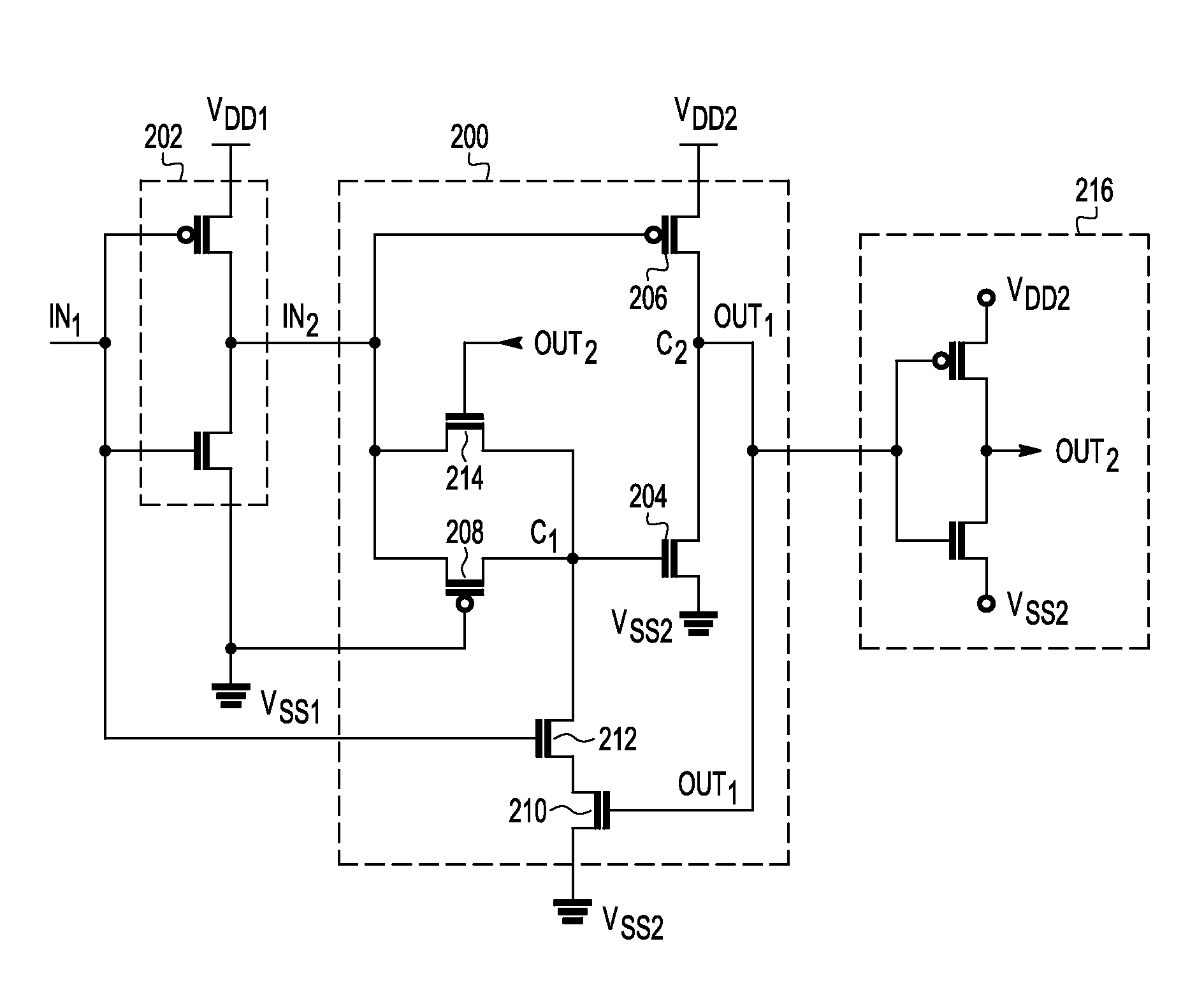
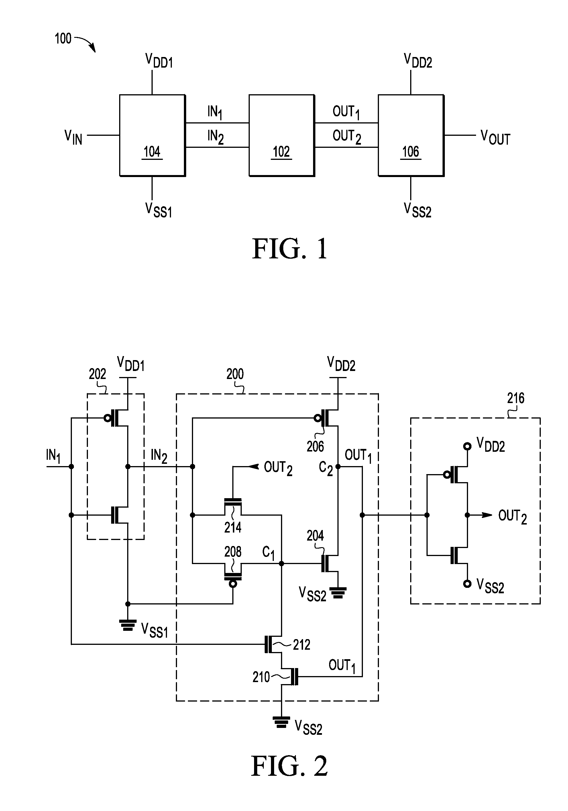
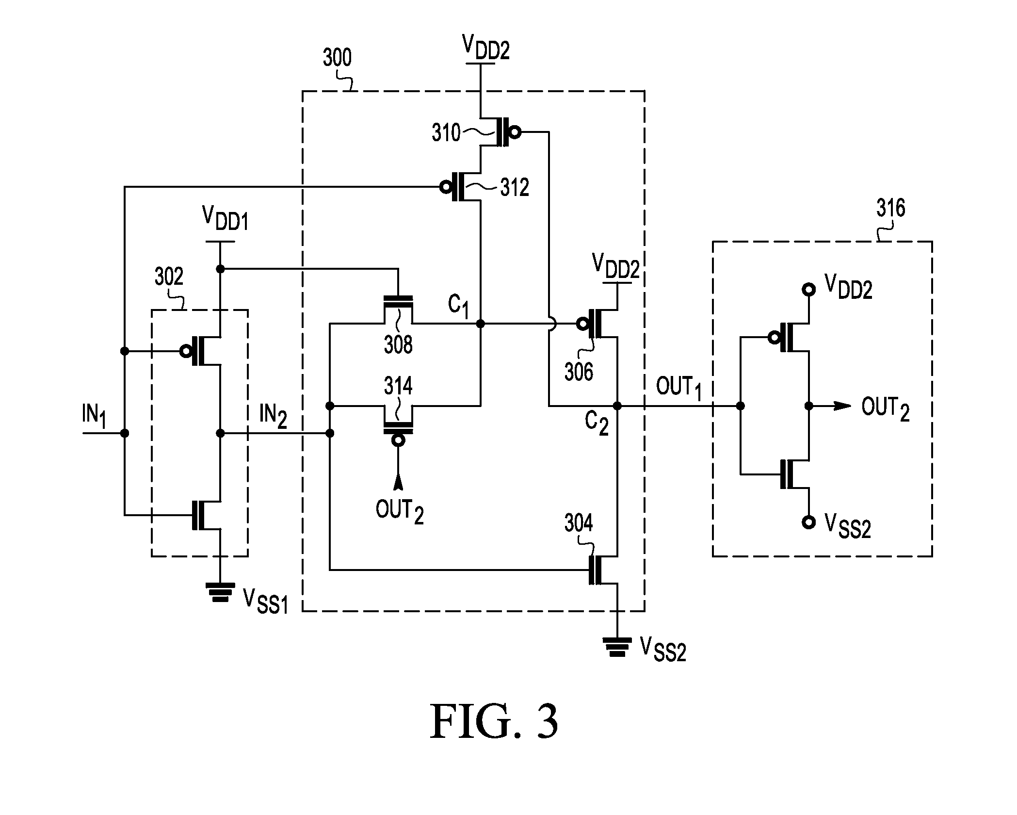
[0010]Level translators may be used in a variety of configurations, system implementations, etc. One particular system implementation may involve translating signals from one level to another in a range near the thresholds of the translator's constituent transistors. For example, a level translator may be used to translate a source-biased input to an unbiased source on a different voltage domain.

[0011]Depending on the configuration, it may also be necessary and / or desirable to be able to translate levels for one or more aspects of a given input. For example, a level translator may be operable to translate two different voltage levels (e.g., a top rail voltage and a bottom rail voltage) associated with the same input. Depending on the configuration, however, the level translator may be operable to translate only one aspect, and / or only one aspect at any one time.

[0012]In order to manage contentious internal nodes (i.e., those nodes at which a plurality of components attempt to provid...


PUM


Abstract

An output circuit, between a first power supply terminal and a second power supply terminal, receives a first logic signal that switches between a first logic state based on a voltage at the first power supply terminal and a second logic state based on a voltage at the second power supply terminal and provides a second logic signal, complementary to the first logic signal. A level translator is in a second power supply domain configured to have a second voltage differential between a third power supply terminal and a fourth power supply terminal, wherein the second voltage differential is greater than the first voltage differential. The level translator is designed so that it may be implemented using a subset of the transistors that have the shortest channel length and narrowest channel width.

Description

BACKGROUND[0001]1. Field[0002]This disclosure relates generally to level translators, and more specifically, to ratioless, near-threshold level translators.[0003]2. Related Art[0004]Level translators take advantage of different techniques to manage contentious internal nodes, particularly at levels near the thresholds of the constituent transistors. As electronic device continue to grow smaller, new techniques are required to manage these contentious nodes while also managing size, energy use, and other design issues.BRIEF DESCRIPTION OF THE DRAWINGS[0005]The present invention is illustrated by way of example and is not limited by the accompanying figures, in which like references indicate similar elements. Elements in the figures are illustrated for simplicity and clarity and have not necessarily been drawn to scale.[0006]FIG. 1 illustrates a high-level block diagram of an example level translation system, in accordance with certain embodiments of the present disclosure;[0007]FIG. ...

Claims


Application Information

Patent Timeline
Patent Type & Authority Applications(United States)
IPC IPC(8): H03K19/0185
CPCH03K19/018528H03K19/018521
Inventor WILLIAMS, JACOB T.CUNNINGHAM, JEFFREY C.RAMANAN, KARTHIK
Owner NXP USA INC
Learn More