Method for adjusting furnace atmosphere in continuous annealing furnace (as amended)

Inactive Publication Date: 2015-11-12
JFE STEEL CORP
View PDF4 Cites 3 Cited by
  • Summary
  • Abstract
  • Description
  • Claims
  • Application Information

AI Technical Summary

Problems solved by technology

Performing such an ope

Method used


Image

  • Method for adjusting furnace atmosphere in continuous annealing furnace (as amended)
  • Method for adjusting furnace atmosphere in continuous annealing furnace (as amended)

Examples


example

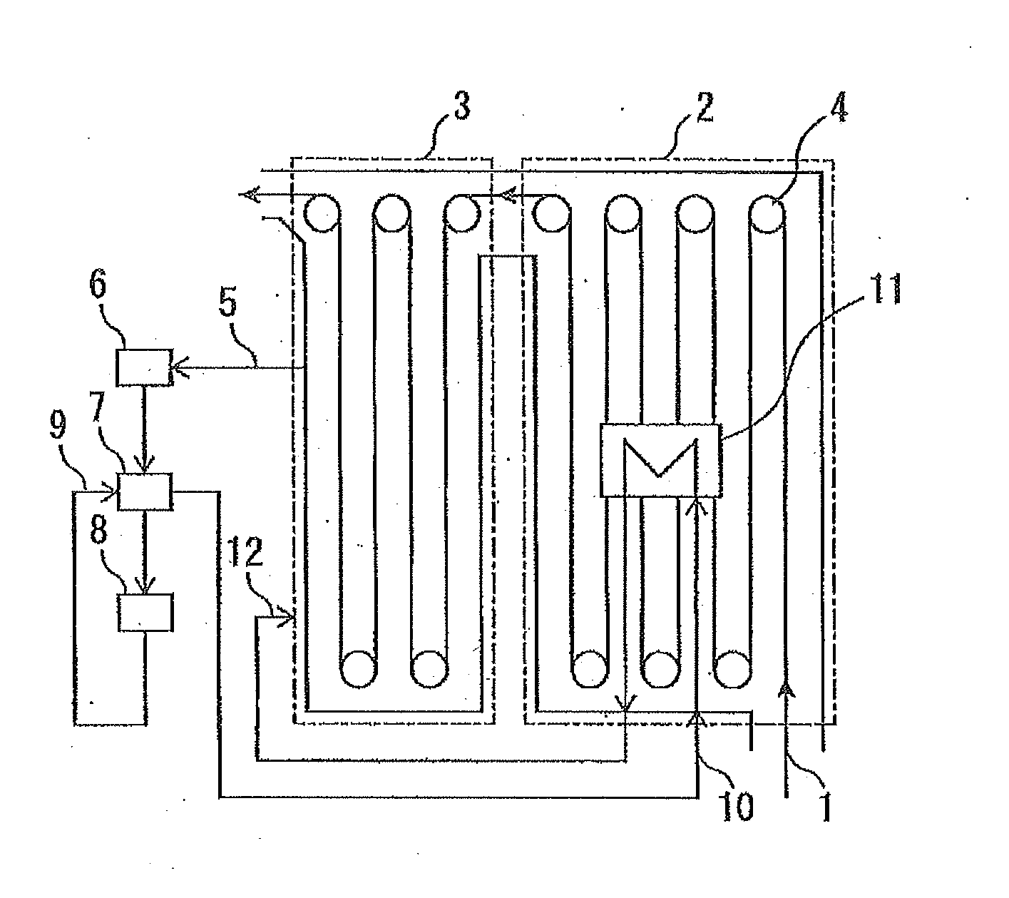
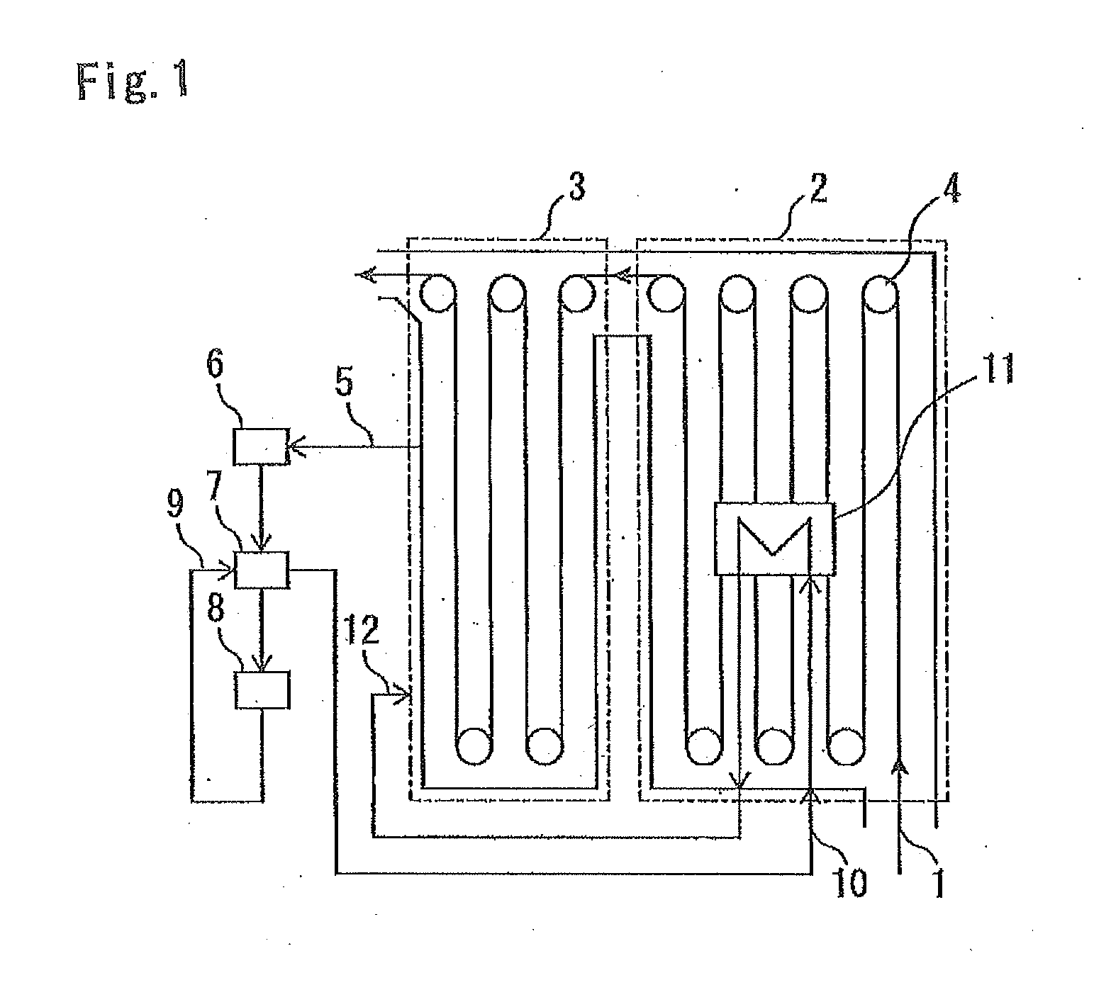
[0015]As an example according to the present invention, in FIG. 1, the burners of the first heating zone 2 and the second heating zone 3 were respectively operated under constant loads, and the furnace temperature was set at 800° C. Under such conditions, the flow rate of a gas treated by the refiner 8 (=injection flow rate) was set at 200 Nm3 / hour, and the gas was injected along the gas flow path shown in FIG. 1. The temperature of the gas immediately before being injected (referred to as the “injection gas temperature”) and the furnace temperature in the second heating zone 3 after injection of the gas (referred to as the “post-injection second heating zone temperature”) were measured. As a comparative example, in FIG. 1, the heat exchanger in furnace 11 was not used, and the gas heated by the heat exchanger 7 was directly injected into the second heating zone 3. In other respects, the comparative example was the same as the example according to the present invention, and the same...


PUM

PropertyMeasurementUnit
Temperatureaaaaaaaaaa
Dew pointaaaaaaaaaa

Abstract

A problem with existing technologies that, when decreasing the dew point of the inside of a continuous annealing furnace by using a refiner, a decrease in the temperature of a part of the inside of the furnace cannot be prevented without supplying additional heat, is to be solved. Provided is a method for adjusting a furnace atmosphere in a continuous annealing furnace, the method including drawing a gas, which is a part of the furnace atmosphere, into a refiner 8 disposed outside the furnace and dehumidifying and deoxidizing the gas; causing the gas that has been dehumidified and deoxidized and that has exited the refiner 8 to exchange heat with a gas that is to be drawn into the refiner 8 in a heat exchanger 7 disposed outside the furnace; causing the gas to exchange heat with the furnace atmosphere in a furnace heat exchanger 11 disposed in the furnace; and reinjecting the gas into the furnace.

Description

TECHNICAL FIELD[0001]The present invention relates to a method for adjusting a furnace atmosphere in a continuous annealing furnace. In particular, the present invention relates to a method for adjusting a furnace atmosphere in a continuous annealing furnace for the purpose of decreasing the dew point of a furnace atmosphere gas in a continuous annealing furnace and efficiently producing a steel sheet having good coatability.BACKGROUND ART[0002]Regarding continuous annealing furnaces, which are used to continuously heat treat a steel sheet (more specifically, a band steel), it is known that the dew point of a furnace atmosphere gas is adjusted to be −45° C. or lower in order to improve the chemical conversion treatment property and the coatability of a high tensile steel sheet after heat treatment.[0003]When starting up a continuous annealing furnace, the inside of the furnace is filled with the atmosphere gas, and the inside of the furnace and refractories in the wall of the furnac...

Claims


Application Information

Patent Timeline
IPC IPC(8): C21D9/56C22C38/00F27D7/06C21D1/76
CPCC21D9/561F27D7/06C22C38/00C21D1/76C21D1/74F27B9/28F27D17/004
Inventor TAKADA, MOTOKITAKAHASHI, HIDEYUKIFUJIL, TAKAMASASATO, NOBUYUKI
Owner JFE STEEL CORP
Why Eureka
Try Eureka