Method for controlling the temperature of a gas distribution plate in a process reactor

a technology of process reactor and temperature control, which is applied in the direction of coatings, chemical vapor deposition coatings, electric discharge tubes, etc., can solve the problems of difficult control of plate temperature and gas temperature, control of temperature, and inability to easily modify the temperature of the gas distribution plate b>28/b>, so as to improve the efficiency of semiconductor processing and reactor cleaning, and the temperature of the gas distribution plate can be increased

Inactive Publication Date: 2006-02-02
DONOHOE KEVIN G +1
View PDF18 Cites 3 Cited by
  • Summary
  • Abstract
  • Description
  • Claims
  • Application Information

AI Technical Summary

Benefits of technology

[0009] According to the present invention, a plasma process reactor is disclosed that allows for greater control in varying the functional temperature range for enhancing semiconductor processing and reactor cleaning. The temperature is controlled by splitting the process gas flow from a single gas manifold that injects the process gas behind the gas distribution plate into two streams where the first stream goes behind the gas distribution plate and the second stream is injected directly into the chamber. By decreasing the fraction of flow that is injected behind the gas distribution plate, the temperature of the gas distribution plate can be increased. The increasing of the chamber temperature results in higher O2 plasma cleaning rates of the deposits on the hotter surfaces. Additionally, where other processes would benefit from warmer gas distribution temperatures, the high gas flow allows higher temperatures to be achieved over the non-split flow of the prior art.

Problems solved by technology

This makes the plate temperature and gas temperature difficult to control as the process puts a heat load on the plate.
Unfortunately, the temperature of the gas distribution plate 28 cannot be easily modified in this arrangement.
The inability to control the temperature causes other problems during different stages of use of the process reactor.
One problem is that cleaning of the interior cannot be easily performed since the temperature is fixed as the gas distribution plate is thermally coupled to the reactor wall during cleaning.
It is helpful to run the cleaning process at much higher temperatures than during the etching process, but such an effective cleaning temperature cannot be achieved since the temperature is controlled by the constant gas flow at the gas distribution plate.
Another problem is that process modifications cannot be performed since only a set maximum temperature is possible and no higher temperature is available that would allow different processes to be performed that require hotter temperatures than those otherwise possible in a fixed-temperature reactor.
The inability to vary the temperature range also hinders the cleaning ability of the reactor.

Method used


Image

  • Method for controlling the temperature of a gas distribution plate in a process reactor
  • Method for controlling the temperature of a gas distribution plate in a process reactor
  • Method for controlling the temperature of a gas distribution plate in a process reactor

Examples


Embodiment Construction

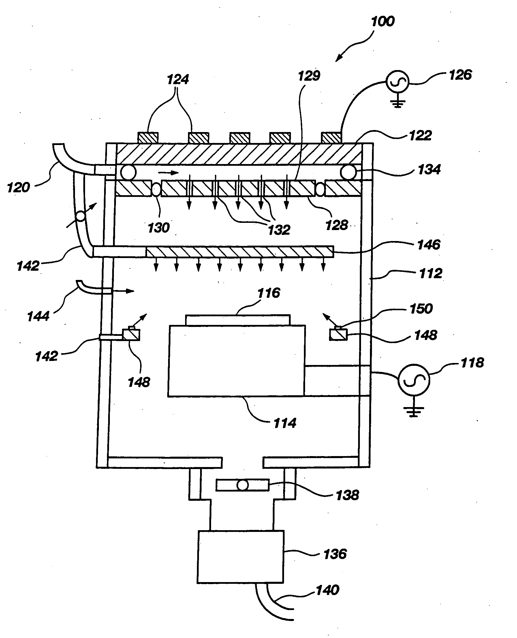
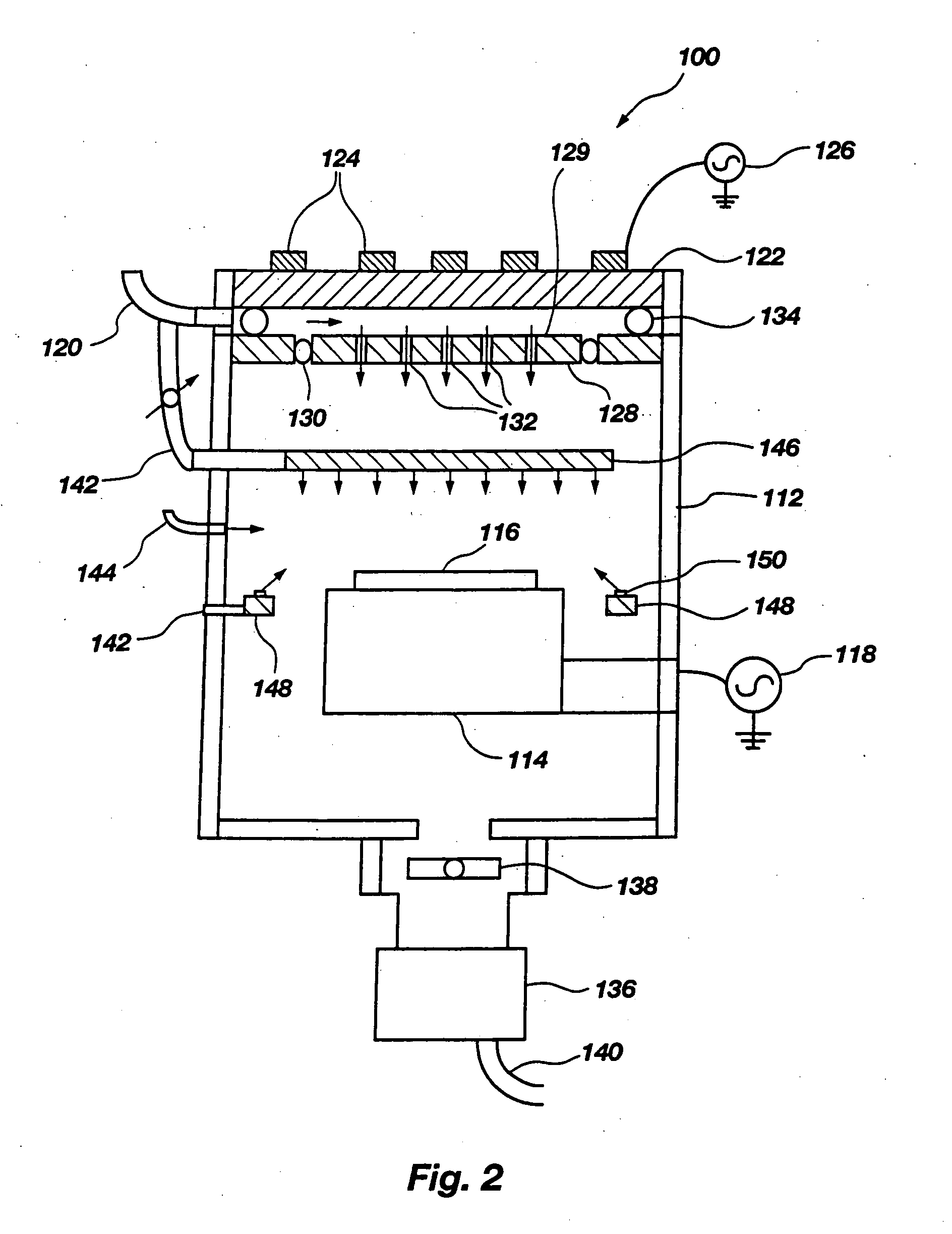
[0014] A high density plasma process reactor 100 is depicted in the schematic diagram of FIG. 2. The reactor may have multiple plasma sources where one source is for etching layers in a semiconductor substrate while the other source is for depositing a polymer. Reactor 100 is a low pressure reactor that operates at or below 50 milliTorr. Low pressure reactors are desired as they avoid microscopic loading, where features of the same size etch more slowly in dense patterns than in sparse patterns. The reactor 100 has separate controls for top and bottom power. The top power is for energizing high density plasma sources and the bottom power or bias source is for directing the plasma for etching and for directing a polymer for depositing. The high density plasma process reactor 100 is modeled after an LAM 9100 TCP (transferred coupled plasma) etcher and an Applied Materials HDP 5300. High density plasma is defined as plasma having an ion density greater than 1×10¹⁰ per centimeter3 in a ...


PUM

PropertyMeasurementUnit
temperatureaaaaaaaaaa
pressureaaaaaaaaaa
temperatureaaaaaaaaaa

Abstract

A plasma process reactor and method is disclosed that allows for greater control in varying the functional temperature range for enhancing semiconductor processing and reactor cleaning. The temperature is controlled by splitting the process gas flow from a single gas manifold that injects the process gas behind the gas distribution plate into two streams where the first stream goes behind the gas distribution plate and the second stream is injected directly into the chamber. By decreasing the fraction of flow that is injected behind the gas distribution plate, the temperature of the gas distribution plate can be increased. The increasing of the temperature of the gas distribution plate results in higher O2 plasma removal rates of deposited material from the gas distribution plate. Additionally, the higher plasma temperature aids other processes that only operate at elevated temperatures not possible in a fixed temperature reactor.

Description

CROSS-REFERENCE TO RELATED APPLICATIONS [0001] This application is a continuation of application Ser. No. 10 / 651,423, filed Aug. 29, 2003, pending, which is a continuation of application Ser. No. 10 / 127,273, filed Apr. 22, 2002, now U.S. Pat. No. 6,617,256, issued Sep. 9, 2003, which is a continuation of application Ser. No. 09 / 944,503, filed Aug. 30, 2001, now U.S. Pat. No. 6,387,816, issued May 14, 2002, which is a continuation of application Ser. No. 09 / 514,820, filed Feb. 28, 2000, now U.S. Pat. No. 6,323,133, issued Nov. 27, 2001, which is a divisional of application Ser. No. 09 / 026,246, filed Feb. 19, 1998, now U.S. Pat. No. 6,132,552, issued Oct. 17, 2000.BACKGROUND OF THE INVENTION [0002] The present invention relates generally to process reactors used in fabricating semiconductor devices and, more particularly, to the control of the plasma temperature within the process reactor for improved reactor fabrication and maintenance operations. Plasma process reactors are used for...

Claims


Application Information

Patent Timeline
Patent Type & Authority Applications(United States)
IPC IPC(8): C03C25/68C23C16/44C23C16/455C23C16/507H01J37/32H01L21/00
CPCC23C16/4405C23C16/45508C23C16/45565C23C16/4558H01L21/67109H01J37/321H01J37/3244H01J37/32522C23C16/507
Inventor DONOHOE, KEVIN G.BLALOCK, GUY T.
Owner DONOHOE KEVIN G
Why Eureka
Try Eureka