Turbine blade

A technology of turbine blades and cooling passages, applied in the direction of blade support components, engine components, machines/engines, etc., can solve problems such as unconsidered, uneven temperature distribution, etc., and achieve improved stress conditions, long service life, and enhanced heat conduction Effect

Inactive Publication Date: 2009-09-16
SIEMENS AG
View PDF0 Cites 3 Cited by
  • Summary
  • Abstract
  • Description
  • Claims
  • Application Information

AI Technical Summary

Problems solved by technology

In particular, current cooling schemes do not take into account the uneven temperature distribution that develops during turbine blade use

Method used


Image

  • Turbine blade
  • Turbine blade

Examples


Embodiment Construction

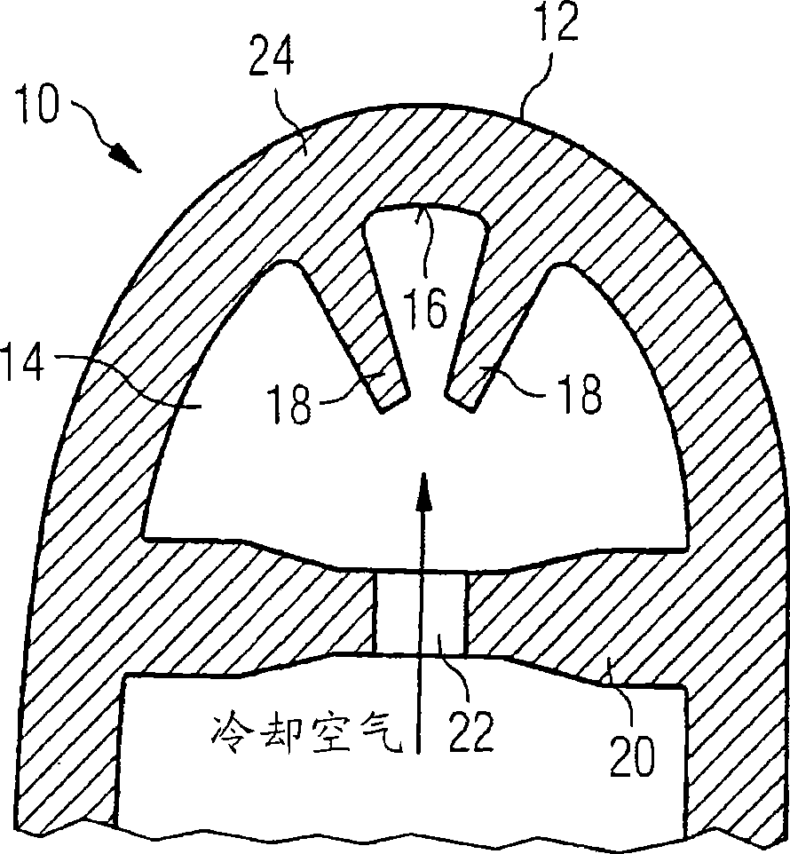
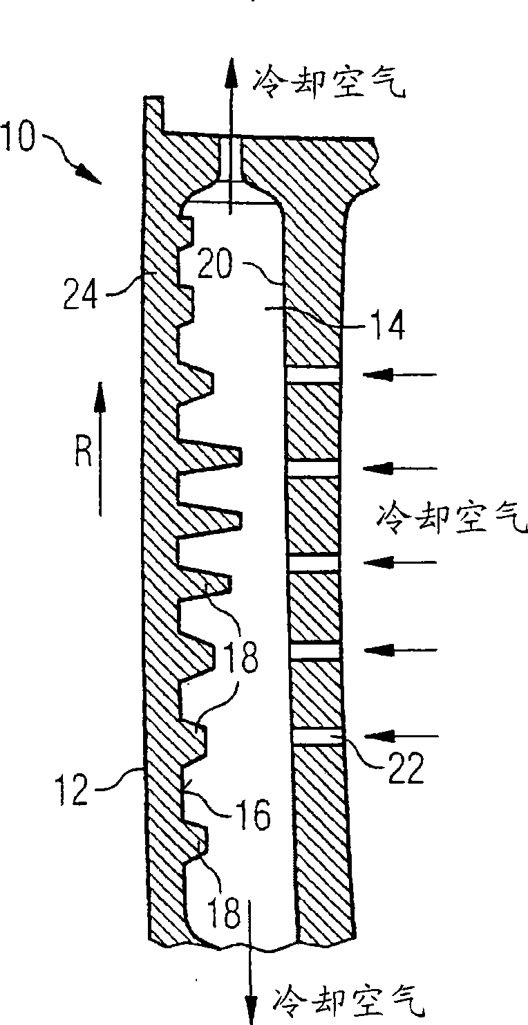
[0026] figure 1 The blade front section of a turbine blade 10 according to the invention is schematically represented by a section plane at right angles to its leading edge 12 . The leading edge 12 may also be referred to as an intake edge. In the interior of the turbine blade 10, near the leading edge 12, a cooling passage 14 extending parallel to the leading edge 12 (that is, a radially extending passage 14 in an axial flow turbine) is designed, which is separated from the leading edge 12 by a wall Section 24 is the boundary. Tongue-shaped cooling elements 18 extend from the arched wall 16 of the cooling channel 14 into the cooling channel 14 , wherein the cooling elements 18 point with their longitudinal dimensions toward the center of the arc of the wall 16 .

[0027] Boreholes 22 are formed in the rear wall 20 of the cooling channel 14 to supply cooling air to the cooling channel 14 in an impingement-cooling manner from further cooling channels (not shown) formed in the...


PUM


Abstract

The invention relates to a turbine blade (10) comprising at least one cooling element (18) and a cooling duct (14) for conducting a cooling medium therethrough. The at least one cooling element (18) is disposed within the flow of the cooling medium and is designed in a cog-shaped manner. The invention further relates to a turbine blade comprising a leading edge (12), a cooling duct (14) which is formed within the turbine blade (10) for conducting cooling air therethrough and extends along the flow attacking edge (12) in at least some sections, and a number of cooling elements (18) that are successively arranged in a stationary manner inside the cooling duct (14) in the longitudinal direction thereof. Each individual cooling element (18) has a cooling capacity that is adapted to a predefined cooling requirement for the leading edge (12) in the surroundings of the cooling element (18).

Description

technical field [0001] The invention relates to a turbine blade according to the preamble of claim 1 . Background technique [0002] Turbine blades, especially those of gas turbines, are subjected to high temperatures during operation that rapidly exceed the stress limit of the material. This occurs in particular in the region around the inlet edge, where the hot working air flow initially impinges on the blade profile of the turbine blade. In order to enable the use of turbine blades also at high temperatures, it has long been known to cool the turbine blades appropriately so that the turbine blades have a higher heat resistance. In particular, particularly high energy efficiency can be achieved with turbine blades having a high thermal strength. [0003] Known cooling methods are inter alia convective cooling, impingement cooling and film cooling. In the case of convective cooling, the cooling air is channeled into the interior of the blade and the heat is removed by co...

Claims


Application Information

Patent Timeline
Patent Type & Authority Applications(China)
IPC IPC(8): F01D5/18
CPCF05D2240/121F05B2260/2241F05D2260/22141F05B2260/201F01D5/187F05D2260/201F05D2240/303
Inventor 海因茨-于尔根·格罗斯
Owner SIEMENS AG
Why Eureka
Try Eureka